Pantera ignition switches are becoming increasingly rare & expensive as time progresses. With finite options, it may be possible to forestall the purchase of a new switch by doing a rebuild / restoration of your existing switch. Some of the failure modes which are typical are as follows:
A. The key does not eject: this may be caused by dirt and baked grease accumulated over the years either in the mechanical or electrical portion of the switch. In the electrical portion of the switch is where the circular spring resides. If it is broken the repair is beyond the scope of this article and a new switch will be required.
B. Intermittent or no electrical contact: This may be caused by baked grease causing a high resistance connection between the contacts. It can be resolved by a thorough cleaning of the contacts. If the contacts are burnt from high current draw through a high resistance contact which has damaged the contact area, then a replacement switch will be required.
The restoration will be in two parts, the electrical and the mechanical portions.
Removal of the switch:
1. Disconnect the battery cable.
2. Remove the two allen cap bolts and the two metric bolts holding the
steering column to the dash.
3. Drop the column a few inches and have it supported by a box which is high enough to relieve stress on the electrical cables.
4. Remove the two screws that hold the steering column trim in place, there is one on each side. one trim piece covers the ignition switch and the other trim piece covers the directional switch.
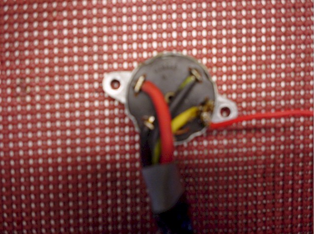
5. Make a wiring diagram of how the switch is wired to the four terminal block up above the column.
6. Unscrew the four terminals holding the ignition switch wires in and
remove the wires.
7. There are two break off security bolts holding the switch housing to the steering column. I sacrificed a sharp center punch to reverse the screws out and it only took me about two minutes to remove these screws with two whacks to the punch with a brass hammer.
8. Remove the whole switch assembly to a clean work area for dissection.
9. Remember how the mechanical portion is indexed to the electrical portion.
10. Remove the screws that hold the mechanical portion to the electrical portion.
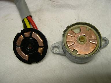
Electrical portion of the switch
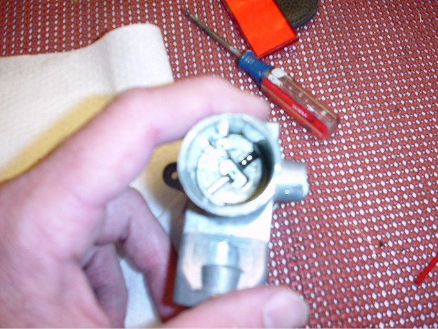
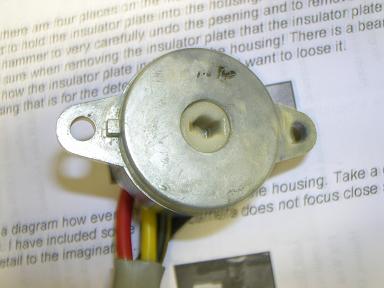
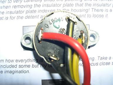
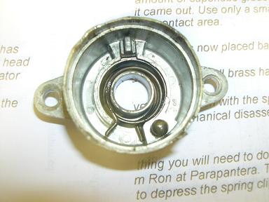
You will see there are four places on the metal switch housing where the metal has been peened to hold the insulator plate into the housing. I used a very small flat head and a brass hammer to very carefully undo the peening and to remove the insulator plate. Make sure when removing the insulator plate that the insulator plate is up. Remember how the insulator plate indexes to the housing! There is a bearing in the switch housing that is for the detent and you do not want to loose it.
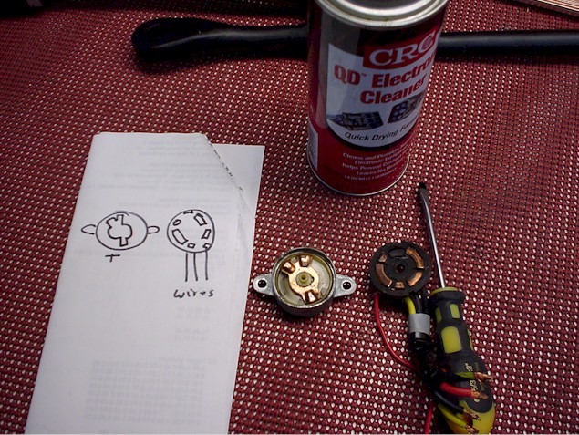
2. Make a diagram how everything is indexed in the housing. Take a digital picture if possible. I have included some but my camera does not focus close so it leaves some of the detail to the imagination.
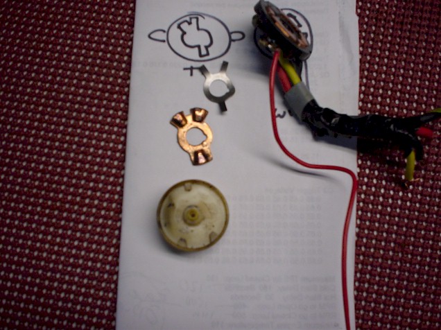
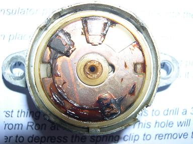
3. Remove the copper/brass contact plate, the plastic guts, the circular spring etc.
4. Clean all parts with CRC contact cleaner, "will not melt plastic". Use surgical gloves to protect your hands.
5. Inspect all parts, if the spring is broken or if the brass contacts
are fried beyond use, you will need a new switch.
6. My switch was just filled up with old cooked grease, a cleaning was all I needed.
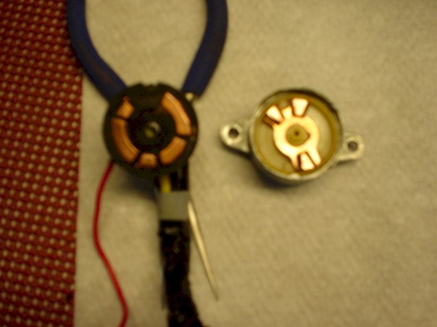
7. Clean off the copper contacts. Both the rotating triangular piece and the contact area on the insulator plate using a brass brush and do it carefully so as to not to damage the contacts. You want them clean and bright. Clean off all grease and then use contact cleaner to remove any residue from the copper contact area
8. If the contact area is cooked, but not too badly it may be possible to have a plating shop re-plate the assembly using nickel then copper or use cool-amp or some other means to renew the contacts, not my expertise!
9.Use a small amount of superlube grease in the housing and re assembled everything as it came out. Use only a small amount of superlube as you do not want any grease in the contact area.
10. The insulator plate is now placed back into the metal housing and
Peened in place using a small brass hammer.
This may solve the problem with the spring not pushing the key back out, if not you will need to do the mechanical disassembly as it may be dirt causing friction in the tumbler.
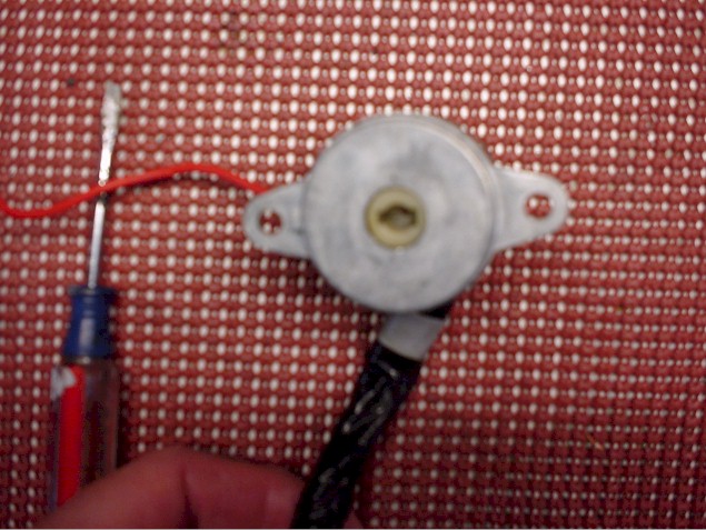
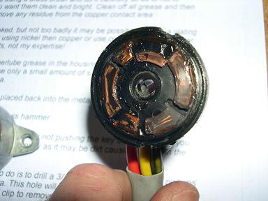
11. The first thing you will need to do is to drill a 3/16 hole as depicted in the pictures provided from Ron at Parapantera. This hole will allow you to insert a small screwdriver to depress the spring clip to remove the tumbler.
![]()
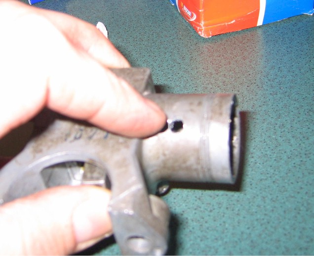
Spring clip and hole location
Note: To determine exactly where to drill I put a ruler on the picture provided by Ron and made a scale on it. I then measured from the reference points on the picture and compared them to the same points on the real switch. I ratioed the measurements to determine exactly where to drill the hole.
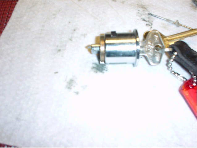
12. With the tumbler out you will now have two sections. The tumbler housing section and the main housing section.
To clean the tumbler section you will need to remove the tumbler from the tumbler housing. KEEP THE KEY IN THE TUMBLER FROM HERE ON!!! Failure to do so will result in all the pin plates falling out
Note: make sure you understand where all the small parts, springs etc go as you dissect this part of the switch assembly. Particularly in the main housing.
13. With the key in, remove the small roll pin at the end of the tumbler body. The end plate will come off and the tumbler will come out of the housing. Use contact cleaner to degrease the tumblers. You can re lubricate it with graphite spray or whatever makes you happy. I used Remington gun lube with Teflon. KEEP THE KEY IN!!
14. Reassemble the tumbler into the tumbler housing, put the end plate on, drive the roll pin back in.
15. To disassemble the main housing there is a very small roll pin in the side of the housing. You need to drive it into the housing and remove it. The inside rotating assembly will now come out allowing you to clean and lubricate the inside of the housing. You will see the two springs that provide the tension for the column lock mechanism in the very bottom of the housing. Clean, lubricate, re-assemble, drive the roll pin back in.
16. Reassemble the tumbler housing back into the main housing. It will click securely back in place.
You have successfully completed the rebuild of each section!!
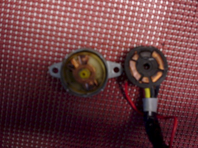
It is time to integrate the mechanical & electrical assemblies
1. Assemble the mechanical portion back to the electrical portion of the switch indexing them as they came apart.
2. Clean off the wires where they will go into the terminal block. I cut the insulation of each wire back an additional 1/16 inch. Use the brass brush to brighten the wires. Degrease the wires with contact cleaner.
3. Twist the wires to make them tight so they will fit back into the terminal block, degrease again after you touch them to twist them.
4. Insert the wires back into their respective terminal locations and tighten securely.
5. Reassemble the balance of the column in the reverse order you took them apart
6. Hook up the battery and try out the switch
Updated images from Jeff Udelson
Before:

After: