December 18, 2001
When I bought my Pantera in 1998 the engine had been rebuilt in 1991, but only had been run about 8000 miles. The engine had a lot of lifter noise and sounded like it might be a aggressive solid lifter cam. I pulled the valve covers to find stock rocker arms indicating that it was a hydraulic lifter cam. In 1998 converted to Crane adjustable studs and Crane roller rockers so I could adjust the lifter preload. I messed with the preload for a few weeks and it never seemed like the lifters were working correctly. One or more of the lifters was always noisy even with the preload set at 1 1/4 turns. Recently I got tired of the lifter noise and decided to replace the lifters. I talked to CompCams and they recommend that I could replace the lifters without replacing the cam as long as I went though the correct procedures, lube, run-in, etc. This is a debated issue in the engine world but I decided it was worth the risk.
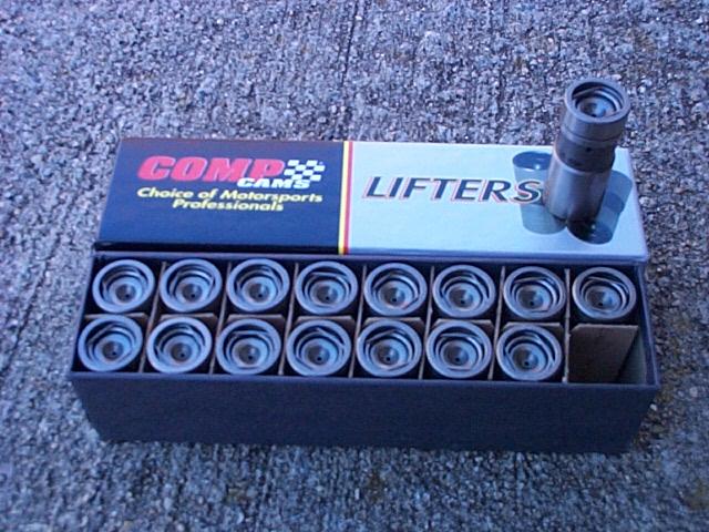
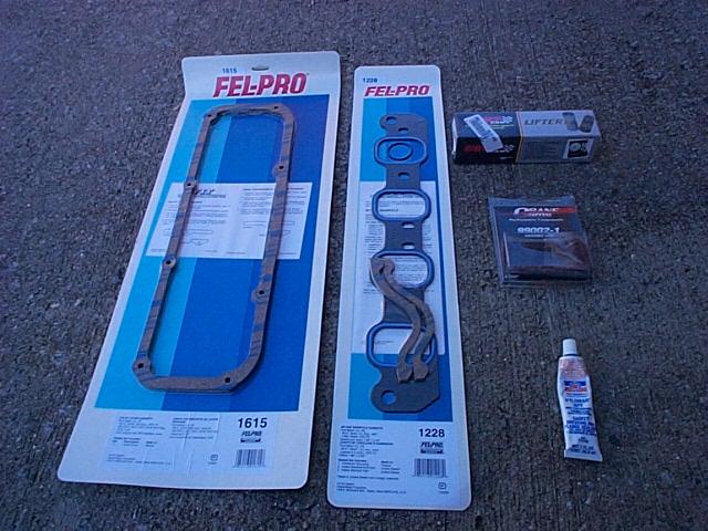
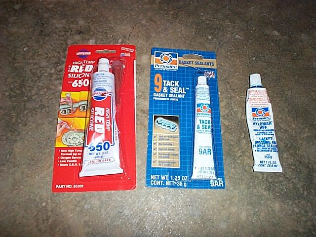
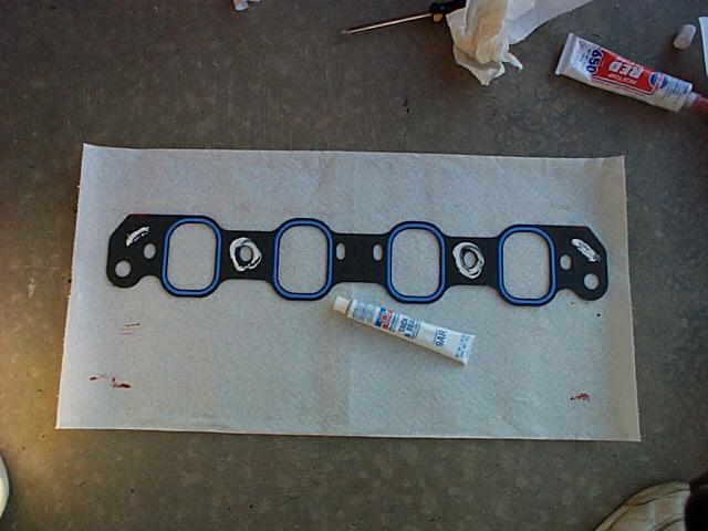
I purchased a new set of CompCams' 832-16 lifters, a Fel-Pro gasket set and gasket sealers. The 832-16 are anti-pump-up lifters that function up to 7000 RPMs. I decided not to go with the original Ford turkey pan intake gasket. I'm not sure if that was good or bad idea.
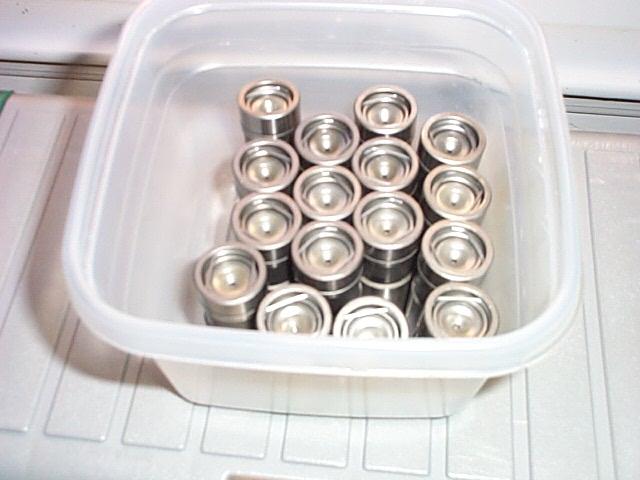
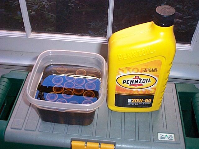
CompCams recommend soaking the lifters in oil over night before installing them. I'm not sure if this did any good but I wanted to follow the instructions.
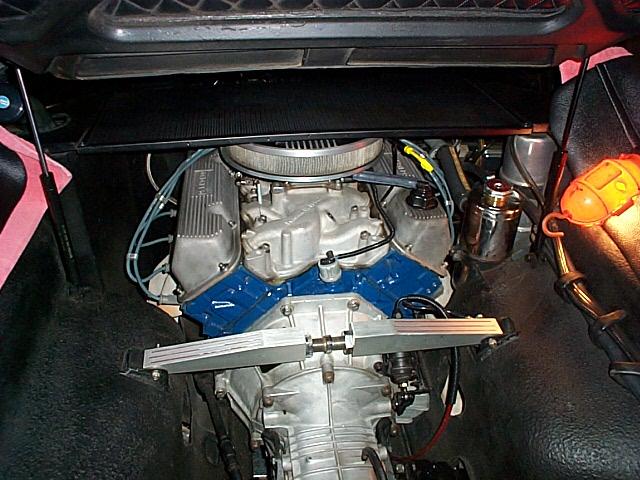
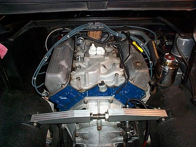
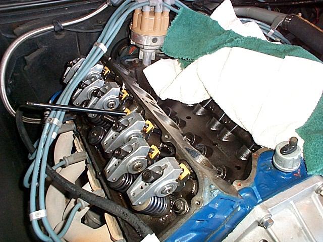
Next, I removed the engine screen, removed the air cleaner and the carb. Note the paper towel in the intake ports, You absolutely do not want to drop anything inside of the engine!
Next, I removed the valve covers.
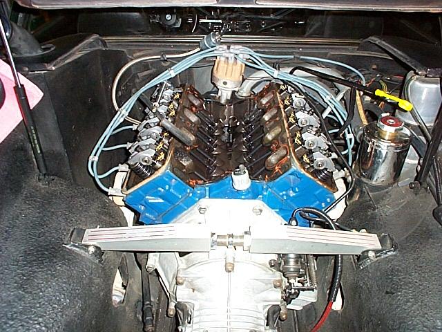
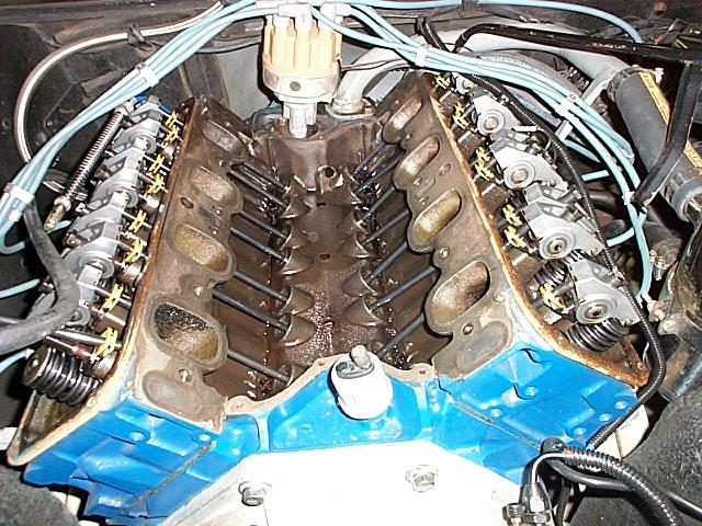
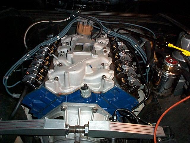
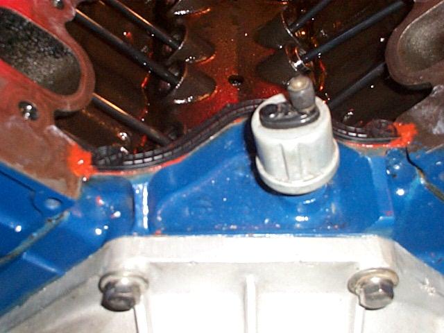
Then removed the intake manifold and carefully cleaned all of the old sealer from the heads and the front and back of the block. I put paper towels in the valley to keep the old sealer from getting in the valley. Do not let any sealer fall into the valley, head ports or the top of the heads.
December 19, 2001
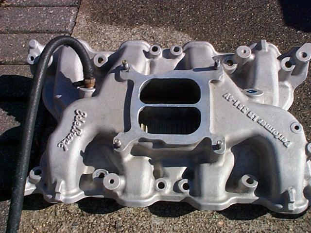
The intake manifold needed some cleaning so I used automotive wheel cleaner, scrubbed it with a brush and finished up with a few applications mag wheel etching cleaner. It looks like new.
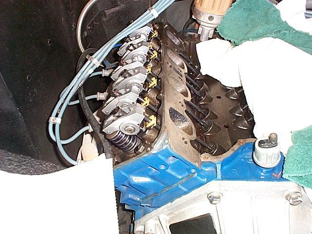
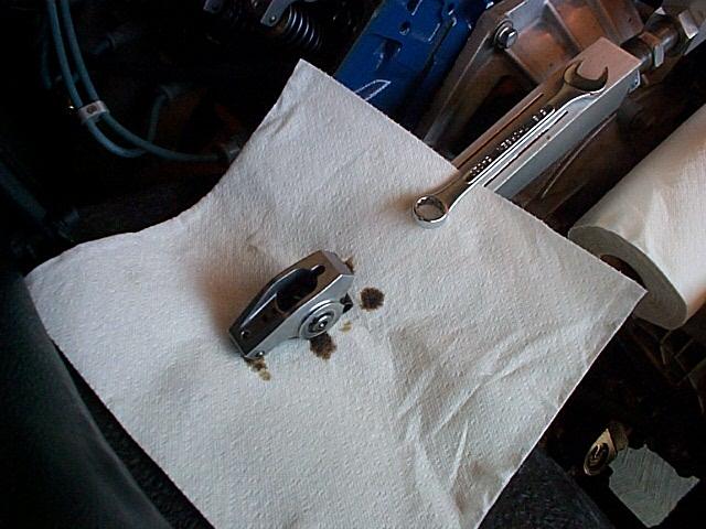
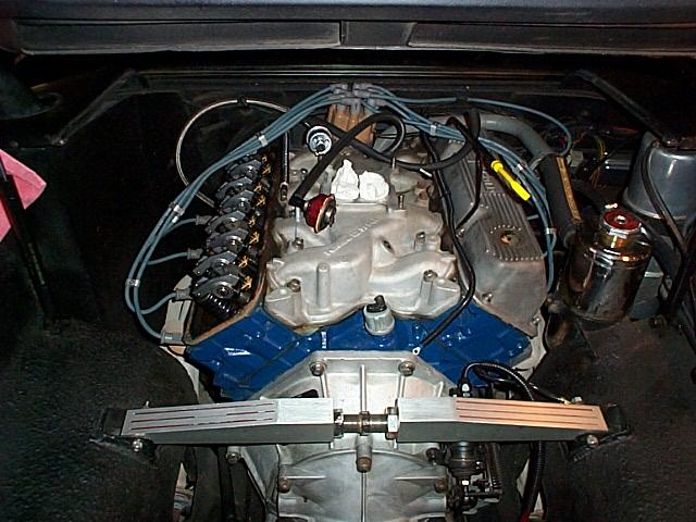
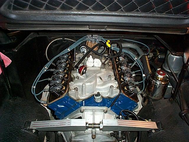
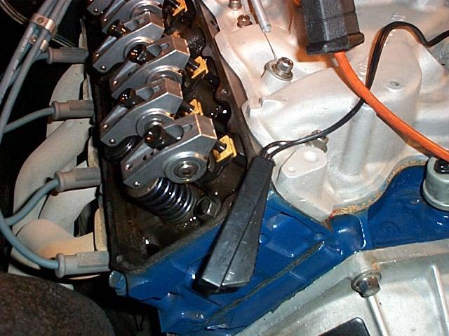
The next steps were to remove each of the old lifters and install the new lifters. I decided to remove one lifter at a time, install the new lifter but not set the preload until I was sure that all of the existing lifters were not damaged. I started on the driver side of the engine, removing the rocker arm, lifting up the push rod and removing the old lifter. I transferred the new lifters out of the oil bath into a new container without oil so I could clean off the bottom of the lifter, apply the Crane Cam molly cam lube and insert the lifter in the block. The push rod was placed in the top of the lifter and the rocker arm installed. I turned down the rocker nut with my fingers and made sure reach rocker arm was loose but that the push rod could not fall out of position.
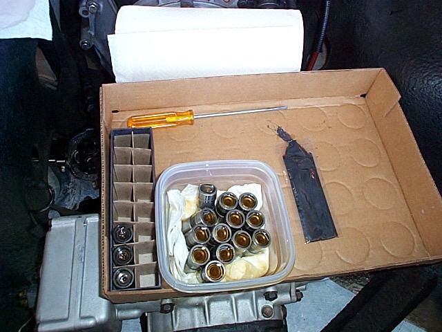
I marked one end of the new lifter box "engine back" and inserted the old lifers so I could keep track of what lifter came out of each position. I thought it might be helpful until I had all of the old lifters out and made sure that the bottom surface of each lifter did not show any cam damage All of the old lifters looked great!
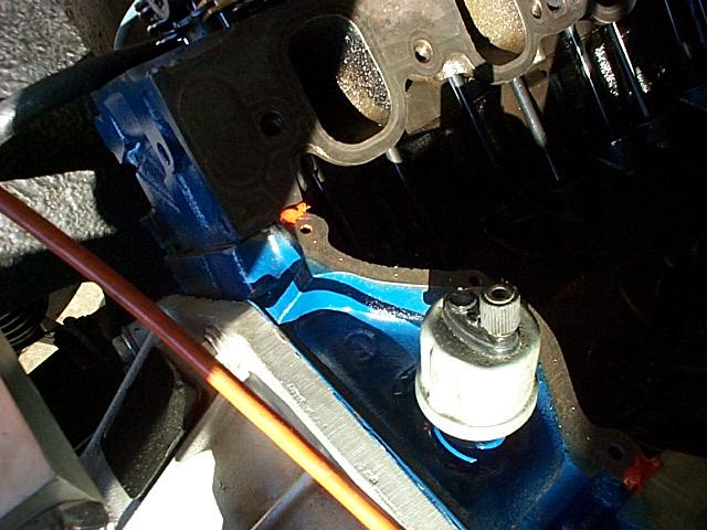
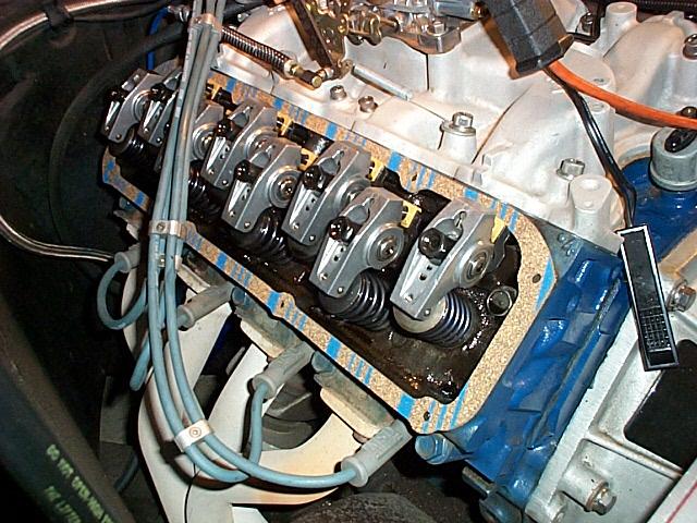
Next, I re-cleaned all of the areas that the gaskets would contact with lacquer thinner to make sure they were supper clean. Red sealer was used in each four areas where head meets the block. The cork gaskets were installed on the front and back of the block and sticky sealer was used to hold main gaskets in place. I forgot to take an image of the gaskets in place but I put some more red sealer on to of the end of the cork gaskets where they met the main gaskets.
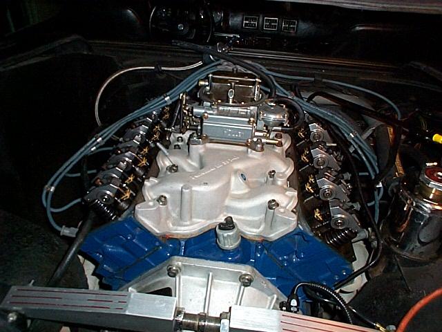
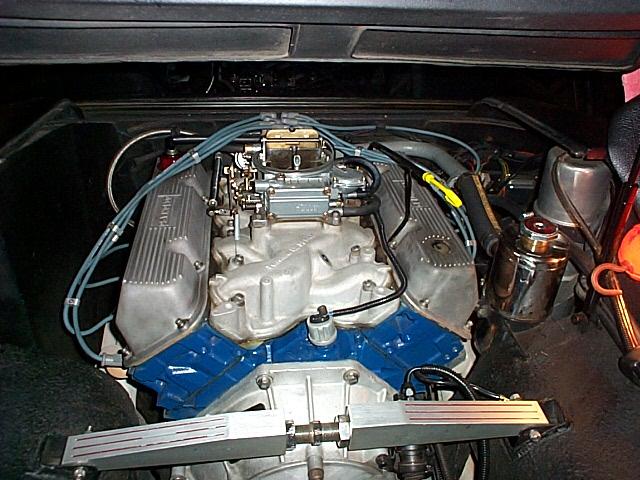
The next step was installing the intake. It went on easy and the gaskets stayed in place. Next, I put the carb on and connected up the fuel line so that I could use the starter to crank the engine over for the lifter preload. I used a little MPF sealer on the manifold bolt threads because they extend into the open valley area.
I disconnected the coil wire and connected my remote starter switch the the terminals of the starter relay. It is important to disconnect the coil wire so that the engine can not start while the starter relay is engaged. I used the remote starter switch to bump the engine around to the positions I needed to adjust each of the lifter preloads. Caution! When using the remote starter switch make sure that you are the only one working on the engine and you are in control of the switch at all times!
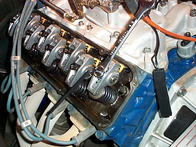
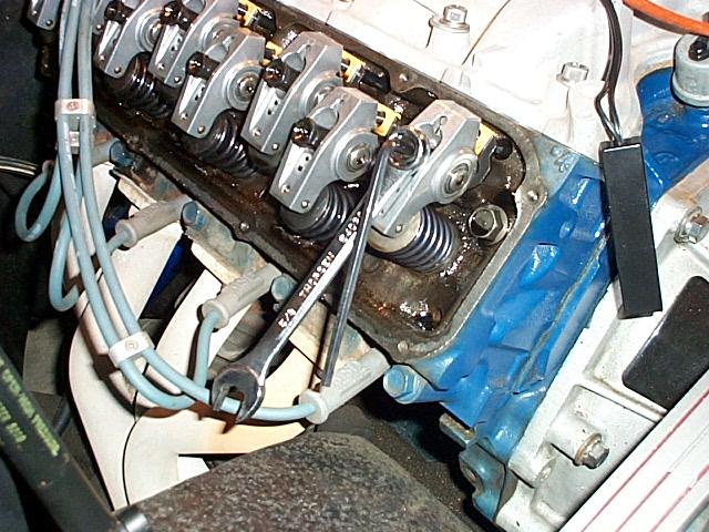
I used the information on the Crane Cams website to position each lifter for the preload setting. The direct link to the PDF file is here. The above images show the 1/2 turn of preload that I used. It takes awhile to do this adjustment but go slowly and make sure that preload is set perfectly. The preload must be adjusted with the lifter fully on heal of the cam.
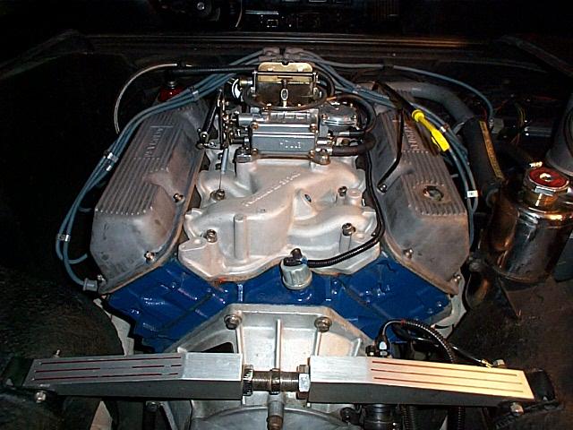
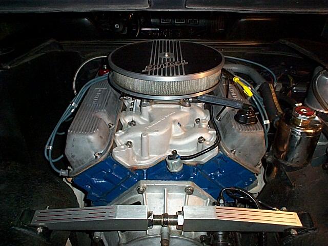
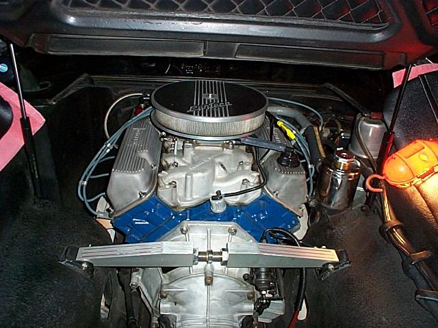
After the preload was set I re-installed the valve covers and then the air cleaner.
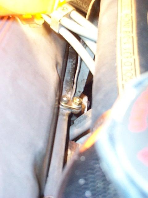
One of the bolts on the passenger side valve cover supports the coolant pipe that runs from the front of the engine thermostat housing to the expansion tank. The support fits over the top on the valve cover edge and makes removing and installing the valve cover a nasty job. I made a short metal link that mounts with the valve cover bolt and extends over the top of the pipe support mounting point. I twisted the bottom of the pipe support so it was beside the valve cover and lined with the link. A bolt and nut is used to mount the pipe support under the link. I got this idea from Dan Jones' Pantera.
December 20, 2001
I turned over the engine a little with the coil wire disconnected to get some oil to the lifters and then started the engine and ran it for 20 minutes at 2000 RPM. I varied the RPM some during the 20 minutes.
So far the lifters sound much better and time will tell how successful the project went. Although the engine oil looked clean after the cam run-in the next step was changing the oil and filter to remove any particles created by the cam run-in.
December 26, 2001
Remember I said that "'Im not sure if that was good or bad idea" using the Fel-Pro gasket. It turns out with my engine setup, that not cutting out the exhaust crossover holes made for a poor running engine when cold. I didn't cut out the crossover holes because I didn't want the hot exhaust to cook oil onto the bottom of the intake manifold and have the carbon fall into the engine. The pan type gasket keeps the hot oil off the intake so I pulled it apart again and installed a Ford type pan gasket NAPA part number MS-15816 (Boss 351C).
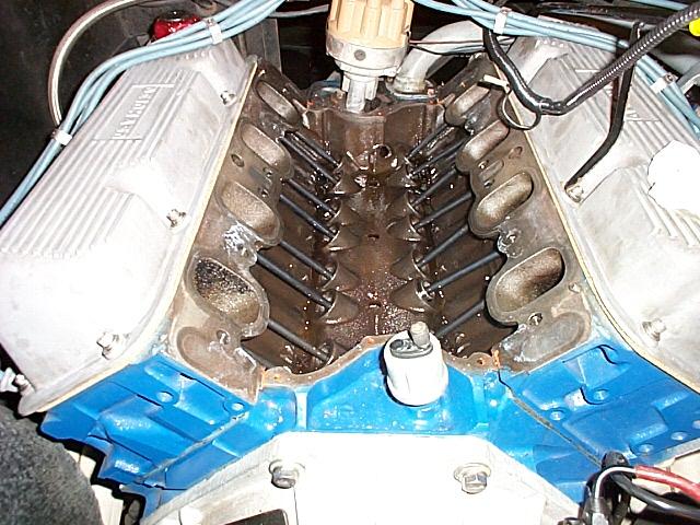
After taking the intake off I re-cleaned the heads and block.
Test fitting the pan.
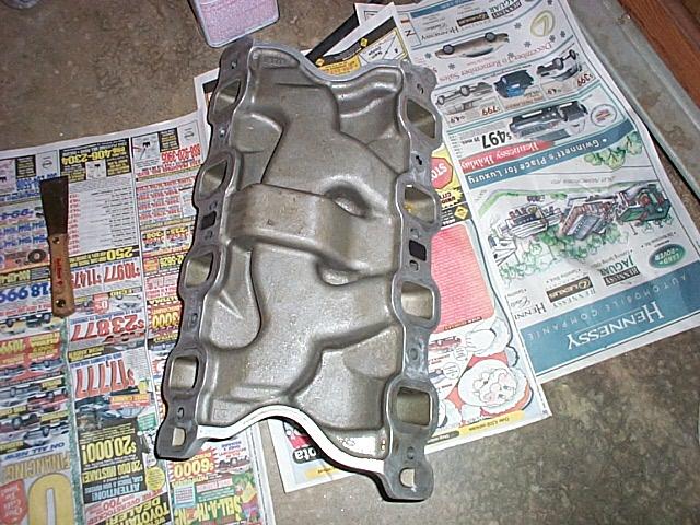
View of the freshly cleaned intake.
View of the back rubber seal with sealer on the ends.
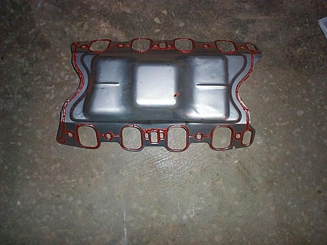
View of the pan with a very small bead of sealer on the bottom side.
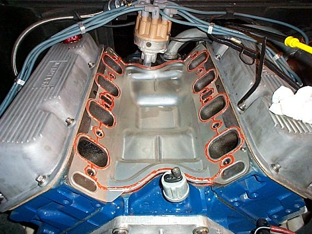
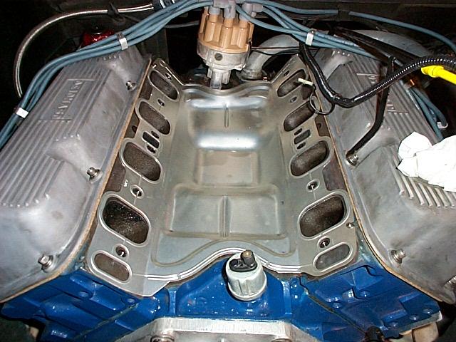
The pan installed on the engine ready for the intake. I ran a very small bead of sealer around the intake ports and ends.
The test drive showed that the engine runs good when cold now that the exhaust crossover is functional.
February 2, 2001
After running the engine for awhile I noticed that the back rubber gasket under the back of the pan was splitting and was sliding out from under the pan. I pulled it apart again and made custom 1/8” thick rubberized cork gaskets for the front and back of the engine. I used a stiff piece of photo paper and laid it on the block area where the gasket goes and tapped lightly with a hammer to mark the paper with the outline of the block. I cutout the paper and then transferred the shape to the cork sheet using a pen. I cleaned the top of the block with thinner and glued the cork to the block with Stick and Seal. I cut the ends of the cork gaskets at an angle so they fit tightly to the angle of the heads and put high temp RTV under and on top of the ends of the gaskets where they meet the heads. I cleaned the RTV sealer off the intake, heads and pan and resealed it with a very small bead to make sure I didn’t get any vacuum or oil leaks. February 9, 2001, so far so good! I just got back for a lengthy test drive and I do not see any oil leaks.
Hydraulic Lifter Preload
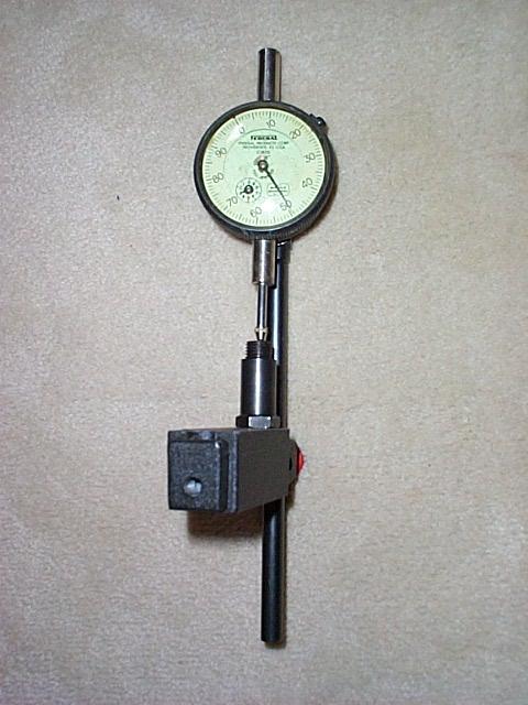
Have you ever wondered how much 1/2 turn of a Crane Cams 351C Polylock adds to the preload. I spent some time with a dial gauge and a Polylock and found that 1/2 turn is .025 and one full turn of course is .050. Comp Cams specifies .020 to .040 lifter preload and Crane Cams specifies .020 to .060.