March 15, 2002
When I purchased my Pantera all of the handbrake cables, linkage and linkage mount were missing. All I had in place was the handbrake lever. Because the Pantera handbrake does not work very well it is common for owners to remove all of the cables and linkage and junk them. The other problem is that the stock Pantera linkage mount is welded to the inside of the frame rail and gets in the way when the coolant hoses are changed, etc. In my case someone had completely cut the mount off the frame.
Pantera Performance has developed a removable bolt on handbrake linkage mount and I decided that it would be a good way to restore my hand brake system. Over the next few weeks I'll be covering the installation of the Pantera Performance handbrake linkage mount and reinstalling the hand brake system on my Pantera.
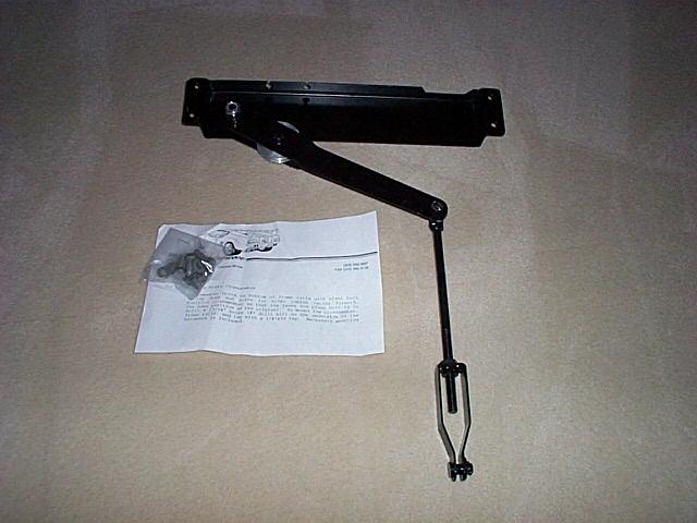
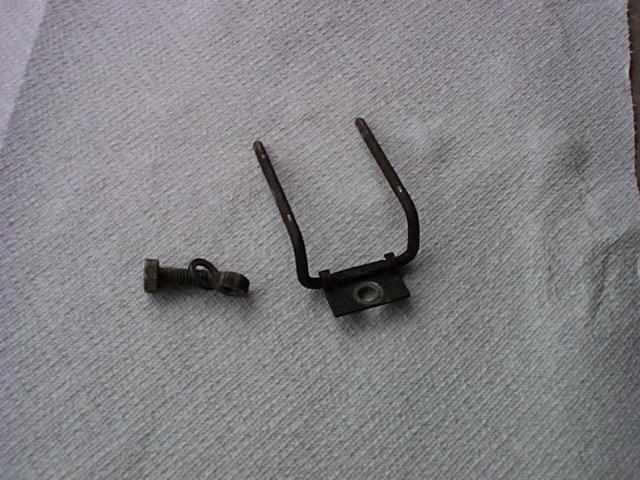
Pantera Performance handbrake linkage mount
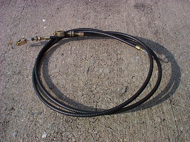
I ordered the Pantera Performance handbrake linkage mount and some refurbished linkage from Pantera Performance. Unlike the original mount. the Pantera Performance handbrake linkage mount bolts to the bottom of both frame rails. The mount has a stud for the linkage attachment and the kit includes bolts to attach the mount to the frame rails. The new handbrake cables will arrive next week along with some cable retainers and new brake pads with the correct extension to keep the caliper piston from turning.
March 25, 2002
Test fitting the handbrake linkage mount
I was concerned about the front to back position of the mount but after some test fitting I realized that as long as it fits OK between the oil pan and the coolant hoses the position was not that important. The key issue was the length of the brake cables and as long as it was not too far forward the position was was fine. After the test fitting I relocated the speedometer cable so it runs behind the lower part of the pan and over the top of the oil drain plug and on top of the brake cables. The brake cables keep the speedometer cable in position.
After finding the best position for the mount I used a builder's square to square the position of the mount with the frame rails and center punched the frame for the mounting holes. Pantera Performance includes 1/4" 20 bolts to attach the mount and recommends drilling the frame rails and tapping then with a 1/4" 20 tap. I drilled small pilot holes first to determine the thickness of the metal and how well the 1/4" 20 tap would work. It didn't look like the metal was thick enough for the tap to work very well so I used #14 X 1/2" hex head sheet metal screws that I threaded into under sized pilot holes. The under sized holes expand to make more threaded area than the tap and hex head sheet metal screws tightened the bracket to frame very well. The car needs to be raised up pretty far to get the drill motor and drill under the frame to drill pilot the holes.
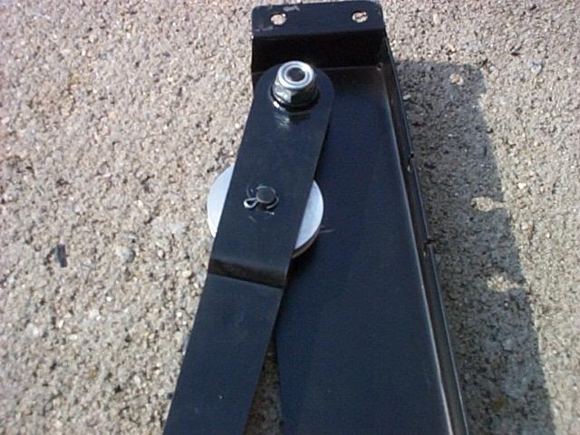
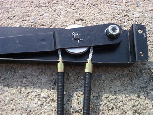
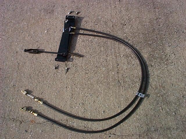
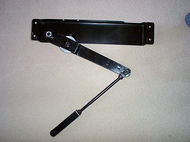
Images of the linkage mount and cable assembled. The longest cable goes on the passenger side of the mount. Light grease was used for lubrication on the rotating points of the mechanism.
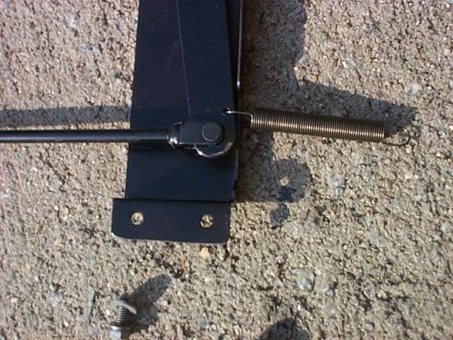
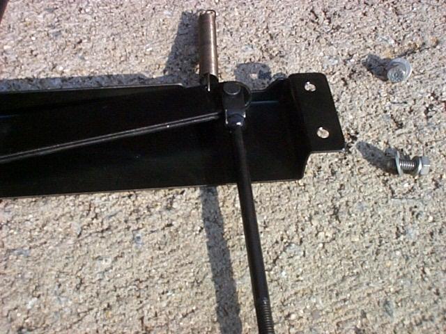
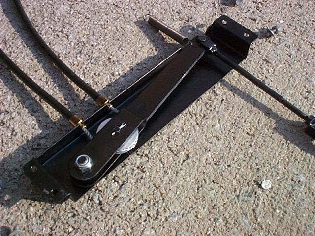
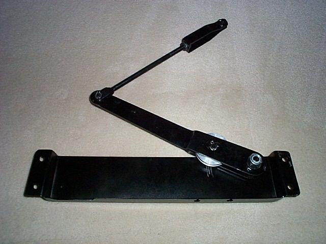
Image of the return spring connected to the arm.
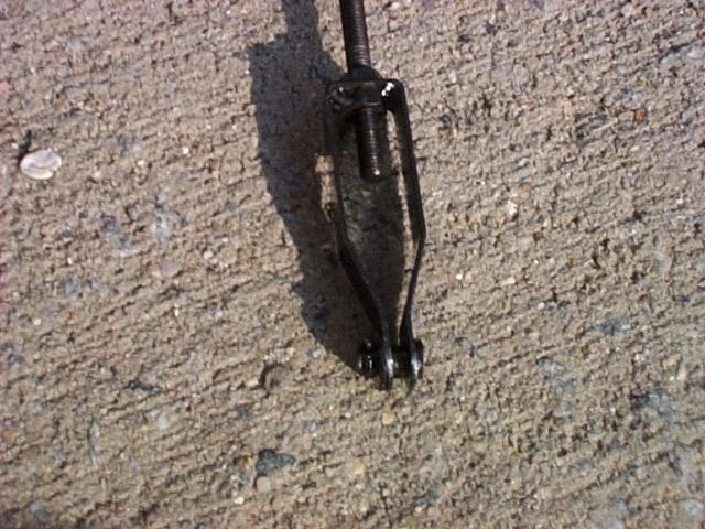
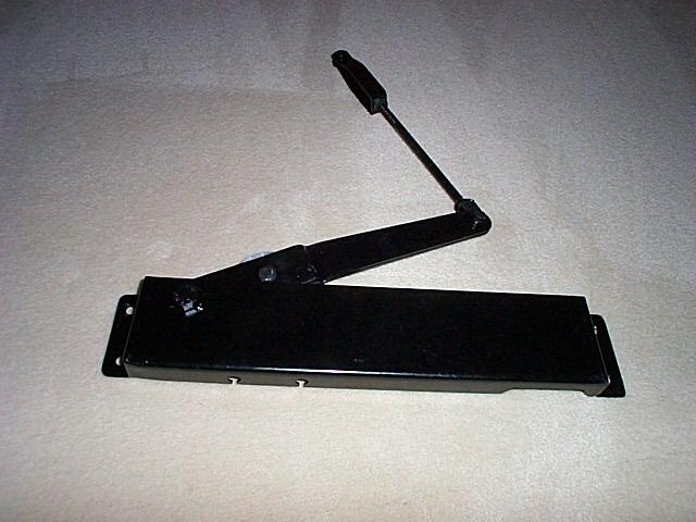
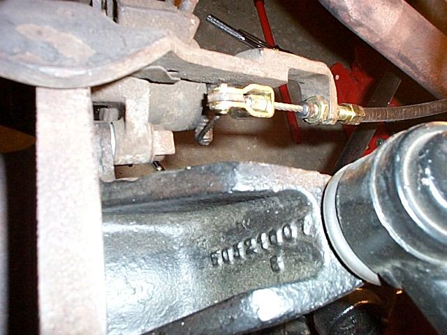
Image of the clevis that connects to the bottom of the handbrake lever.
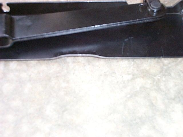
To make sure that the linkage mount had a lot of clearance with the coolant hose I reworked the edge of the bracket.
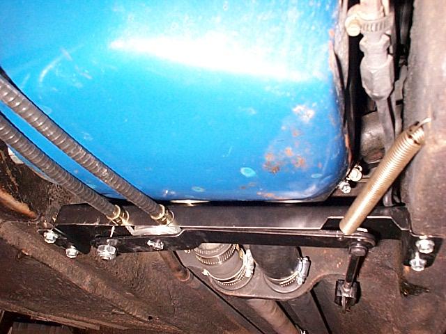
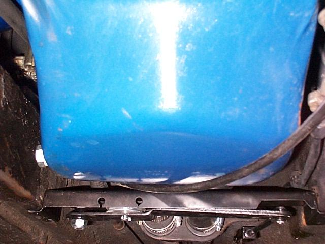
View of the completed linkage mount installation. I adjusted the handbrake connecter link clevis so that the equalizer arm was as far back as possible without hitting the edge of the mount. I found the original hole in the frame for the return spring.

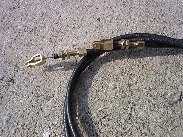
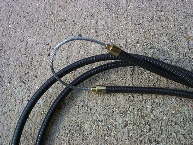
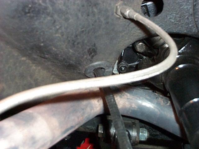
View of the cable connection. The small rubber water seal must be slid off of the outer cable cover so that the cable end adjustment nut can be moved over the cable and the inside cable slid into the key hole on the inside caliper bracket. The outer threaded part of the cable can then be inserted on the caliper arm and the nut threaded back on and the rubber seal reinstalled.
The cable end adjustment nuts are used to take the slack out of the cable but make sure that the handbrake caliper arm can return all the way to the plastic stop and to the full home position. If the caliper arm does not return to the home position the self adjusting ratcheting mechanism will not work.
The cable slack adjustment is only related to the home position of the handbrake equalizer arm and the caliper arm home position. I set the home position of the hand brake equalizer arm as far back as possible without it hitting the back edge of the mount (see above image). This adjustment is made using the clevis that attaches to the bottom of the handbrake lever. Once this adjustment is set, the cable ends at the calipers can be adjusted so there is no (or very little) slack in the cable where it goes around equalizer arm wheel and with the caliper arms in the home position (rotated to the outside of the car) the cable end clevis have about 1/32 end play to make sure that the caliper arms will be able to fully return to the home position. To remove slack in the cable move the threaded end of the cable cover to the inside of the car. Remember the cable is a loop so try to keep the right and left side of the cable threaded end adjusted to about the same length. This is not a super critical adjustment but too much cable slack will make the hand brake lever bottom out before the brakes set and too little will cause the caliper arms not to fully return to the home position, miss the ratchet teeth and the handbrake will not self adjust.
At this point I got lucky and found that the ratcheting mechanism inside of the calipers still worked and with a little Tri-flow lube on the caliper arms the hand brake actually works. At least it locks the rotors so they will not turn by hand while the car is still on jack stands! There is a ratcheting mechanism inside of the calipers that automatically adjust the handbrake for the ongoing brake pad wear and the ratchets themselves can wear rendering the handbrake inoperable.
March 26, 2002
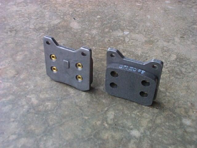
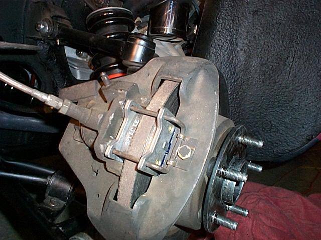
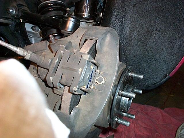
View of the correct brake pads
The brake pads on my car did not have the correct extension that keeps the caliper piston locked in position. I ordered new and correct brake pads from Pantera Performance.
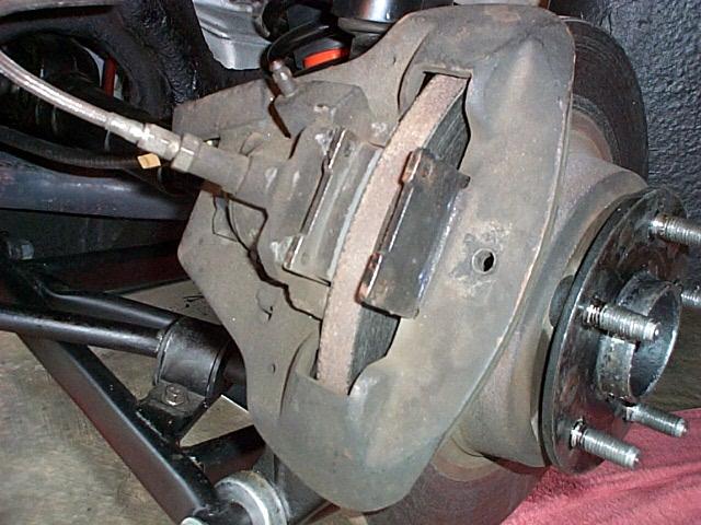
Removing the old brake pads
The anti-squeal spring clip is removed first, then the retaining bolt and nut for the retaining wire and then the pads can be lifted out.
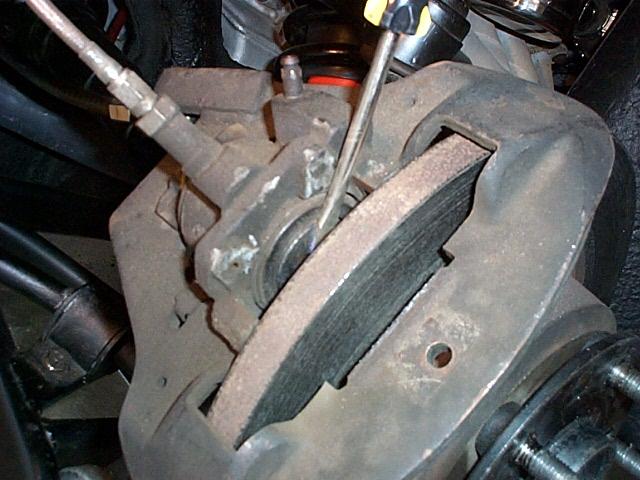
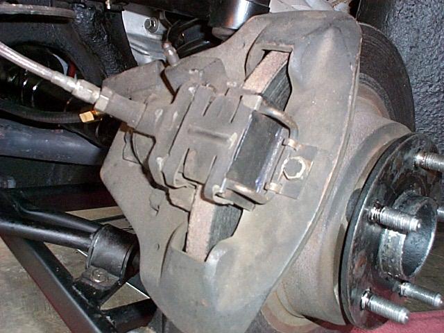
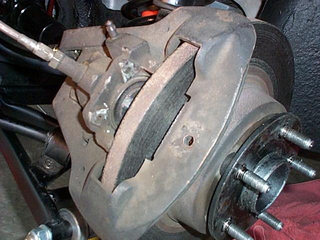
View of the caliper piston
The caliper piston is engaged with the handbrake ratchet so the piston must be rotated before the caliper can be compressed to install the new brake pads. I use a screw driver in the locking slot to rotate the piston and then expand the caliper. Make sure that the brake master cylinder has enough extra space for the brake fluid to backup when the caliper piston is moved. The piston must be rotated back to the home position so that the locking extension on the back of the pad will holed it.
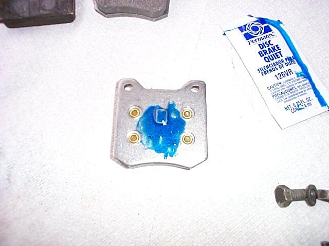
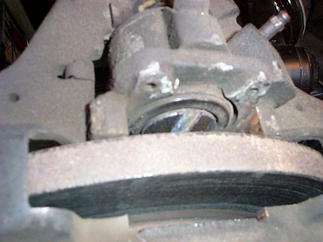
Anti-squeal compound being applied to the back of the pad
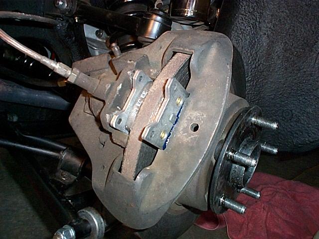
View of the new pads being installed
Next the new pads are inserted into the caliper, the locking wire installed and the anti-squeal spring clip installed. The pads should not be a tight fit at this point. Make sure the extension on the inside pad correctly engages the slot in the caliper piston.
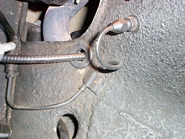
Wheel house grommet
The last item was installing the wheel house grommet to protect the brake cable. I used some rubber grommets that I got at the local ACE hardware store and cut them to make the installation easer.
The handbrake should start engaging snugly at about five clicks as the handbrake handle is pulled up. With a little luck the handbrake should actually work!
March 27, 2002
Made a test drive today to test the bakes. Everything works great including the handbrake!
Update - April 20, 2002
Today I discovered that the handbrake lever release button was sticking in the down position and not letting the ratchet lock the lever when the handbrake was pulled up. It acted like the button was sticky, as if it needed some lube. To lube the lever ratchet mechanism, the handbrake lever boot must be removed from the floor and the two bolts that hold the lever removed. The clevis pin must be removed from the bottom of the lever and then the lever lifts out.
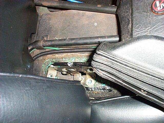
View of the bolts that hold the lever mechanism to the floor
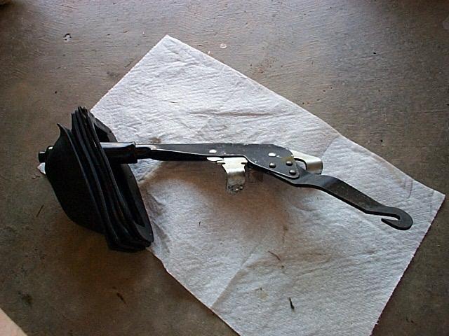
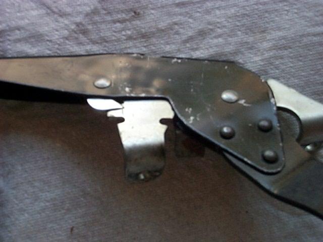
The lever was bent very slightly near the ratchet
After removing the lever mechanism I found that I had apparently bent the lever slightly to the driver side by not pulling the lever straight up when applying the brake. This caused the ratchet to bind. The lever being positioned on the passenger side of the car creates an odd leverage arrangement when pulling up on the lever. I used a vice to hold the lever and bent (adjust) it straight. While I had the lever out I lubed the mechanism. In the future I'll be a little more careful how I pull up on the lever..