By Ralph Granchelli
rgranchelli at esedona.net
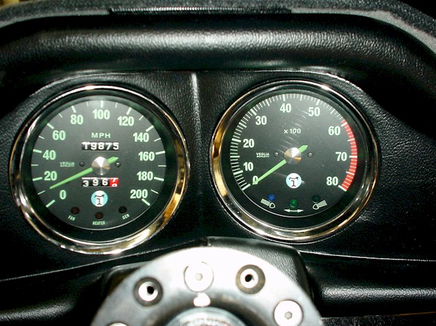
The stock tachometer and speedometer look nostalgic, however they look dated and have poor contrast. Additionally, if you have changed from the stock wheel & tire size combination, the stock speedometer may give false readings.
The stock tachometer is designed to trigger from the approximately 100V voltage pulses generated on the (-) side of the coil on a stock point type ignition. If you have converted to a CDI type system you can no longer trigger from the (-) side of the coil now as the voltage could be 400V or higher and will quickly fry the stock tachometer.
A tachometer adaptor can be utilized. The tachometer adaptor is really just a box with a coil in it which replicates the voltage pulses of a stock coil to trigger the tachometer. Complications can arise using this scheme. The tachometer adaptor coil will break down over time. The CDI tachometer out pin is designed to drive a high impedance load which draws little current. An example would be triggering an EFI computer or driving an electronic tachometer.
When driving a tachometer adaptor, the load D.C. wise looks like a less than 40Kohm load. Additionally when initially saturating the coil, it takes many amps of current. This can present an unhappy situation for the CDI and can cause the CDI to go into oscillation under transient operating conditions.
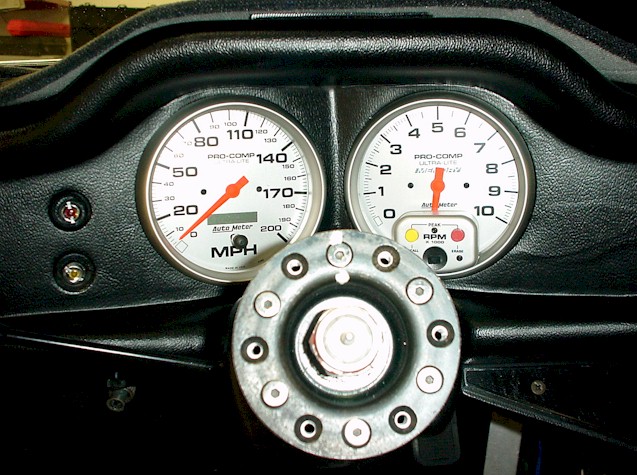
The vendors mostly carry Pantera specific private labeled Auto-meter Pro Comp gauges. They accommodate the idiot lights similar to the stock gauges. They are a reasonable alternative, however they are expensive. Also the speedometer is mechanical which may result in inaccurate readings with tire size changes.
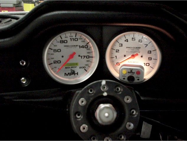
In this article we will install the Auto-meter Pro-Comp Ultra-lite 200 MPH electronic speedometer. The speedometer can be quickly recalibrated in the event of a wheel/tire size change. We will also install an Auto-meter Pro-Comp Ultra-lite electronic memory tachometer.
The idiot lights will be preserved and relocated to the console gauge panel in a custom faceplate.
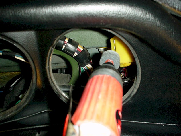
First start the operation by disconnecting the battery. Now remove the speedometer cable, the retaining nuts on the back of the instruments and pull the instruments forward. Disconnect the two connectors,(one for each instrument), the trip meter reset cable and pull the instruments out.
You will need to measure your instrument diameters. In the case of the Autometer gauges the tachometer opening needed about five minutes of careful grinding with a pneumatic die grinder to take about 1/8 " out. For the speedometer, the gauge fit out of the box but was tight so I just made a few passes to make sure it was not too tight.
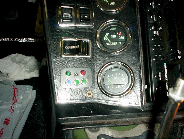
Remove the three screws from the console gauge faceplate panel. Pull the panel forward and remove the bottom dummy switch. We will relocate the idiot lights to this location.
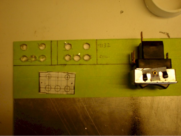
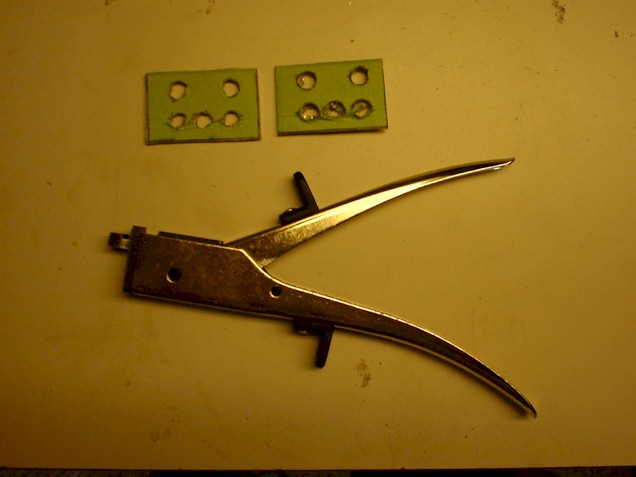
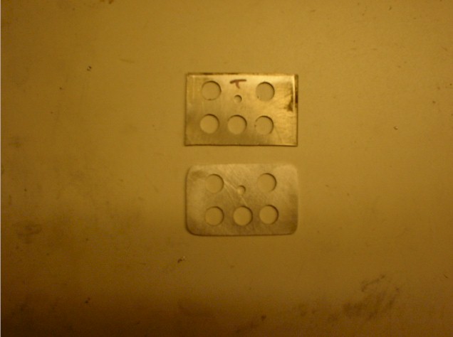
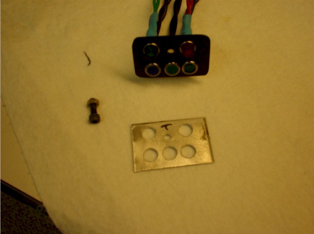
Start by making the idiot light faceplate to relocate the idiot lights. Make two aluminum panels that will cover the original switch hole, one behind and one in front of the panel. Drill holes in the front plate to accommodate your idiot lights. Make the rear panel with holes larger than the front. Drill a small hole for a screw to go through to connect the front and rear panel together over the gauge panel hole. Deburr the holes, sand the face plate with 600 grit sandpaper in a circular pattern to eliminate tool marks. Clean with prepsol. Spray three coats of Duplicolor ceramic low gloss black per instructions. Bake @ 150F for 90 minutes. Mount the lights.
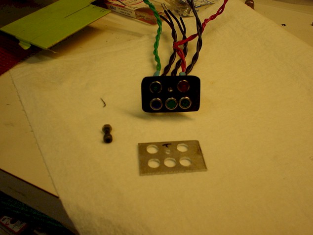
Connect female connectors to each wire coming off of the indicator lamps on the gauge panel. Use a ratcheting crimp tool on each connector. Do not use a hand crimp tool or you are asking for reliability issues. If you do not have a ratcheting crimper, go get one! Use heat shrink tubing over each connector for reliability.
Make an extension harness to connect between the gauge connectors and the new idiot light panel. Make 5 twisted pair cables each 40" long.
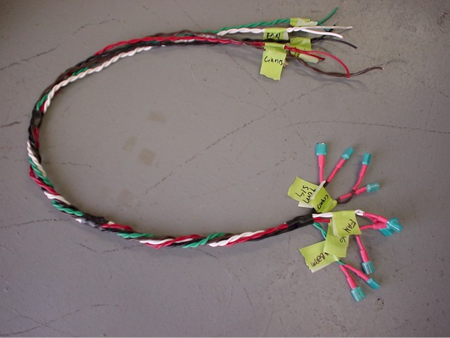
Use different color wire pairs to keep track of the wires. Wrap them all together and secure with electrical tape every 6 inches to keep the cable together. Place labels on the far end of the harness to keep track of which wires go to each indicator. Connect male push connectors on each of the wires to connect to the females of the indicator lamp wires. Connect each wire pair to respective indicator lamps. Make a label for each pair to keep track of the destination.
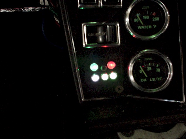
For the light placement, I kept the speedometer idiots on the top with the left being the fan and the right charging. For the bottom row, left is high beam, middle is turn signal and right is light indicator.
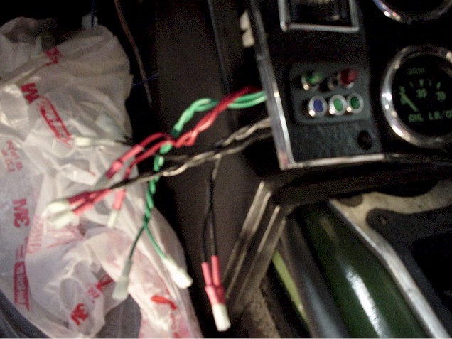
Route the harness up under the consol and cable tie it to the large wire bundle, pull the fan and charge wires through the speedometer opening and pull the rest through the tachometer opening.
Make a large twisted pair to run from the speedometer opening up under the dash, over to the fuse box, thought the rocker, out under the right rear, up by the starter relay following the AC hoses to the rear of the car. Put the harness in cable wrap. I take the seat belt assembly off the inside of the rocker by the passenger seat. Use an electrician fish tape. Go in from the seat belt hole up to the hole by the fuse box and pull a piece of string through. Then pull another string from the seat belt hole to the rear exit under the car. Tie the strings together and pull the harness through. Route the harness following the AC hoses to the area of the ZF angle adaptor.
I was able to procure a square wave signal generator that replaces the angle drive on the ZF. This provides the pulse train to the speedometer such that it can accurately measure speed. They are available from the Speedometer Service Company, 414-463-6660, ask for Roger. I thank Jim Gray for turning me on to this source.
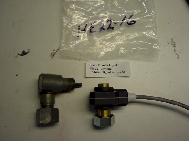
Disconnect the angle adaptor from the ZF and Install the speed sensor.
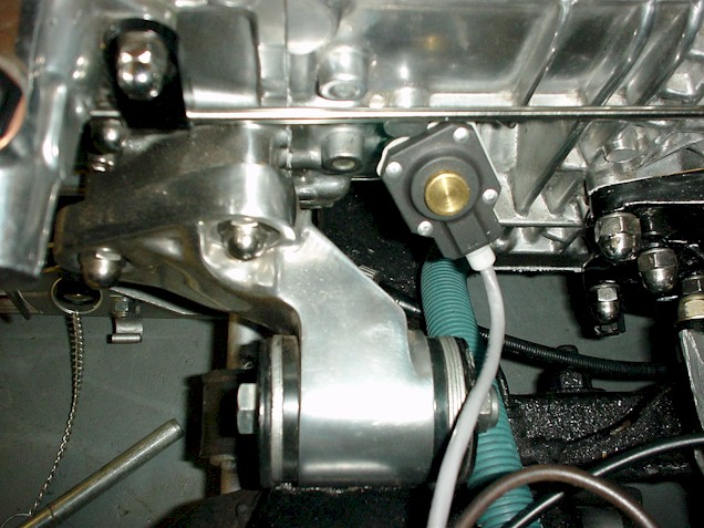
Wire the harness to it using a 3 connector weather-pack or weather-tite connector or waterproof connectors. The black wire goes to the ground in the harness, the speed signal wire goes through the harness to the speedometer and you can pick up switched 12 volts from the old switched 12v connection that used to go to the coil if you are running a CDI.
It is time to wire up the gauges. Please refer to the following handcad generated diagram which defines the pin connections for the speedometer and tachometer.
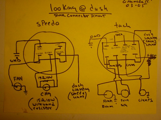
The tachometer and the speedometer connector each contain a ground pin. You will need to construct two ground replicator harnesses that go from the female push connector in the main connector to provide approximately four ground connector points per harness. One ground replicator harness is constructed for the speedometer and one for the tachometer connector ground.
Start with the tachometer indicator light wiring. Attach one wire from the high beam and one wire from the light indicators to ground. The other wire goes to its respective connection point on the connector as shown in the diagram.
One side of your dash lights go to ground and one side to the respective pin on the connector as shown in the diagram.
If you are using a CDI system and are no longer using the wires that were originally connected to the coil you can do the following. Turn the ignition on and with a voltmeter check from ground to each wire. One will have 12 volts and one will have nothing. The one with 12 volts can be used as a 12 volt switched source for your CDI, EFI computer and speedometer square wave generator. The other wire can be tied to the CDI tachometer out pin and the signal will appear on the tachometer connector top row, second pin in from the left. The top row third pin in from the left can be used for switched 12 volts for the tachometer and the speedometer, use an in-line fuse to protest the instruments.
The turn signal indicator light will connect to the bottom two center terminals on the main tachometer connector.
Tachometer ground connects to one of the ground connectors on the ground replicator harness.
Next let’s wire the speedometer. Start with the fan indicator. One wire goes to ground, one wire to the fan terminal on the main connector. The charge indicator attaches to the charge terminals, one on the top right and one on the bottom middle. You will need to put a 15 ohm 10 watt wire-wound resistor across the terminals as shown in the diagram.
I measured the stock resistor to be 14.4 ohms. Do not re-use the stock resistor, now is the time to replace it. I was able to get wire-wound power resistors at Radio Shack and come up with a combination that gave me a little over 14 ohms which works fine.
Wire one side of the speedometer lighting to ground and one side to the dash lighting terminal.
The signal wire from the speed sensor on the ZF hooks to the signal terminal on the speedometer. The ground from the speedometer attaches to ground. Switched 12 volts attaches to the same 12 volts switched as the tachometer.
Check out all the indicator lamps by turning the lights on, turn on the high beams, turn the ignition switch to on and check the directionals, turn the fan switch on, check out that the charge indicator light is illuminated with the ignition switch on and engine not running and goes out upon start up.
Calibrate the speedometer per the instructions by driving an accurate 2 mile distance and going through the calibration procedure.