Disclaimer:
This modification is not approved by Pertronix.
When I bought my Pantera
in 1998 it had an Accel
model 30202 dual point distributor installed.
The 30202 was designed for racing applications and has
the ability to operate at
very
high RPM using points. This is
accomplished with a special bearing that holds the distributor shaft above the
cam, centrifugal advance only and uses points with very heavy spring pressure
to prevent point bounce at high RPM. The
distributor worked very well but the race application points wear pretty fast, requiring ongoing
dwell adjustment and frequent point
replacement. For the last few
years I've
wanted to change out the points for some type of electronic unit but none of
the electronic manufacturers made a conversion kit for the 30202.
I could have just replaced the distributor with a new electronic one,
but because I did not build the engine, I do
not know if the oil pump drive shaft
was installed correctly.
So
removing the distributor could have resulted in the drive shaft falling off
the distributor into the pan.
I knew that the Accel
distributor had some parts that interchange with GM 60s vintage
distributors and after some research I discovered that the 30202 points form
factor is very close to GM points. After
reviewing my options for an electronic unit, I decided the new Pertronix
Ignitor III would be the best unit for
my distributor
modifications. It was small, thin,
used a reluctance head and had great features. It looked like with a few
modifications it would work.
I have spare 30202s that
allowed me to develop and workout the modifications on the bench and then
install the Ignitor III in the
existing distributor that was in the
car. The following are the
modifications to install the Ignitor III.
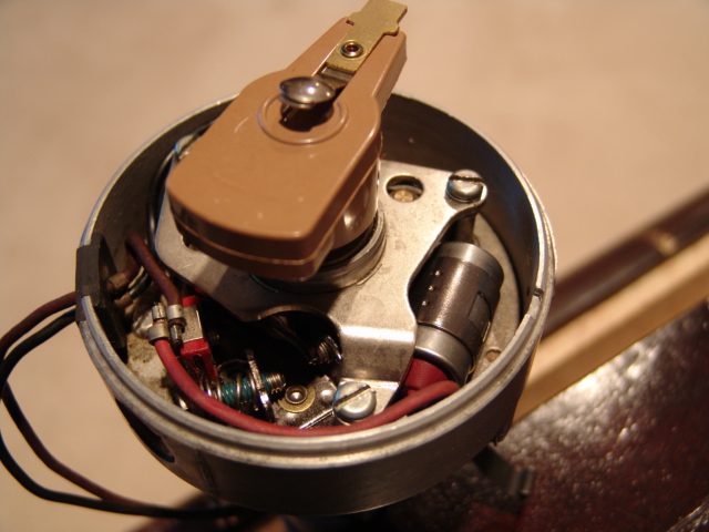
View
of a
spare the Accel 30202
before disassembly.
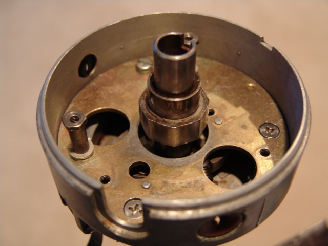
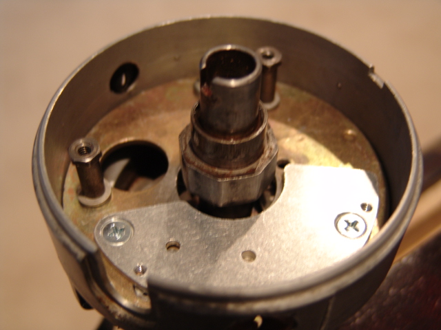
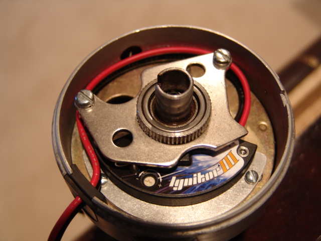
In this view, the 30202
has been disassembled down to the point support plate. The two nearest mount
holes in the plate have been counter sunk with a drill bit and the screws
replaced with flat head screws. The original retaining studs for the secondary
points were reused but thicker washers used to take up the space of the
missing points plus one more thin washer so the bearing plate will clear the
top of the Ignitor
III
reluctance head.
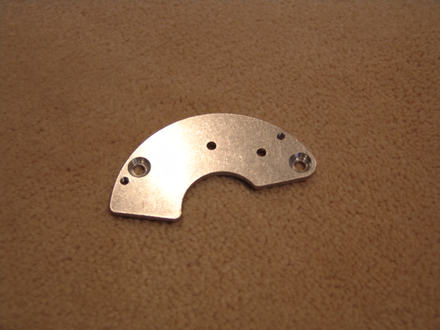
View
of the top side of the Ignitor III GM adapter plate that comes with the Pertronix
kit.
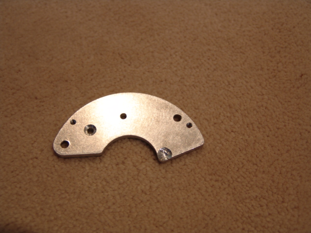
The
lower side of the adapter plate requires modification in two places to make
clearance for the nub that helps hold the points in place and the nub for the
condenser mount. I elected to
modify the adapter plate rather than grinding the nubs off.
View
of the GM adapter installed. It
does not fit symmetrically around the cam but that is not a problem.
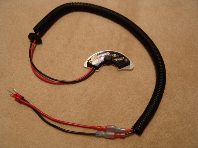
View
of Ignitor III
(Pertronix
part number 71181). I added longer
wires with disconnects and a plastic loom so I could run the wires along the
firewall.
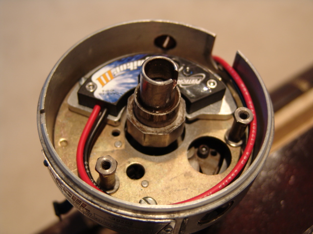
View
of the Ignitor III installed in
the space where the primary points
were located.
At
this point
in the process
I carefully checked the reluctance
head clearance with the high points
on the cam. Pertronix
told me that
the reluctance head should be within .025 of the high points or as close as
possible without touching. Mine
came out around .012. Ignitor III mounting plate holes have a little play in
them so by default it
can be moved around a bit.
Note the height of the reluctance head in the center of the Ignitor III
and the fact that it will be close to the bottom of bearing plate.
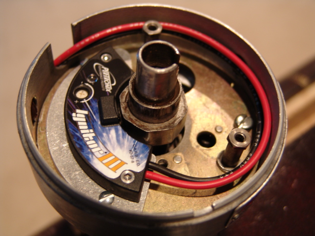
I
decided
to cut off the
arm of the bearing plate that is in
the way of the Ignitor III. The
bearing plate feels secure with just two mounting locations and without the
points,
the side
force on it is light.
I guess it would be possible to run without the plate but I felt that
it would be better to retain the plate.
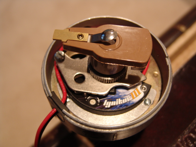
Another view. I decided to use the Pretronx Blaster III coil that is a very low resistance (.32 ohms). The coil is designed for the Ignitor III and capacitive discharge systems and the coil is NOT compatible with points.
Follow
the Pretronx
instructions for setting the Rev limiter, wiring and installation. The
ballast resister must be removed to
use the Ignitor III.
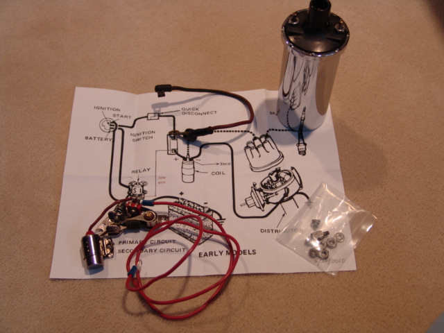
Just
in case, I made an emergency
back up kit with a single primary
point set, condenser, wires, hardware, my old coil and a wiring diagram. I
left my ballast resister on the firewall for now.
After giving the points kit more thought, I bought a backup
Ignitor III
that will be easer to change.
Advantages
of the Pertronix
Ignitor III:
-
Five times more spark energy than points
-
Multi-spark thru the entire RPM range
-
REV limit set by user, 4000 to 9000 accurate to +/- 50 RPM
-
Adaptive dwell maintains peak energy throughout the entire RPM range, reducing misfires while improving engine performance
-
Peak current level is reached just prior to spark for maximum energy without the heat build-up, increasing coil performance and module reliability
-
Adjusts spark timing at higher RPMs to compensate for the inherent electronic delay
-
Senses startup and develops more energy for quicker, easier starting
-
Senses crank orientation from either the distributor cam lobe or a PerTronix magnet sleeve
-
Thermal clad surface mount construction for high performance reliability
-
Memory safe function for user settings
-
LED user feedback for rev limit confirmation
-
Built-in reverse polarity and over current protection shuts down the system, preventing component damage
-
Legal in all 50 states and Canada (C.A.R.B. E.O. #D-57-8)
For more information on Pertronix products http://www.pertronix.com/
Adding Ignition Relay
After running the Pertronix Ignitor III for a few weeks I decided to add an ignition relay to bypass the ignition load on the ignition switch and through the relay provide the Ignitor III fused power directly from the battery lead on the starter solenoid. I wasn't having any problems feeding the power to the Ignitor III through the ignition switch but it seemed like a good idea. This change along with my headlight and cooling fan relays have off loaded all the heavy loads on the ignition switch to relays.
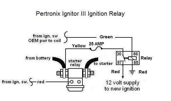
Schematic of the relay system. This drawing was provided by George Pence (Pantera International) and I modified it to meet my requirements and wire colors.
I used a Dorman #84601 30 AMP universal relay and the Buss Fuses #BP/HHG 30 AMP inline blade fuse holder that were purchased from Advance Auto. I expect that the 30 AMP rating for this application is way overkill but I used the higher AMP rating components for reliability. The 25 AMP fuse is more than needed too, but I was interested in reliability.
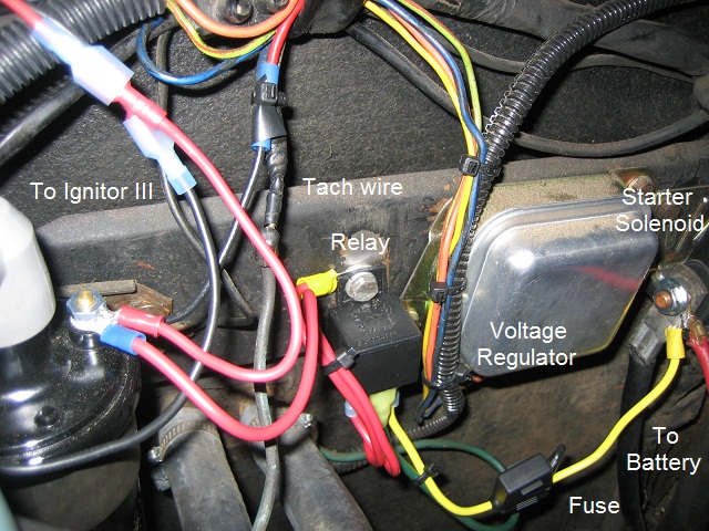
View of the relay installed with the parts labeled. The relay It is bolted to the location where the ballast resistor was located and I used the relay mounting bolt to ground the relay.
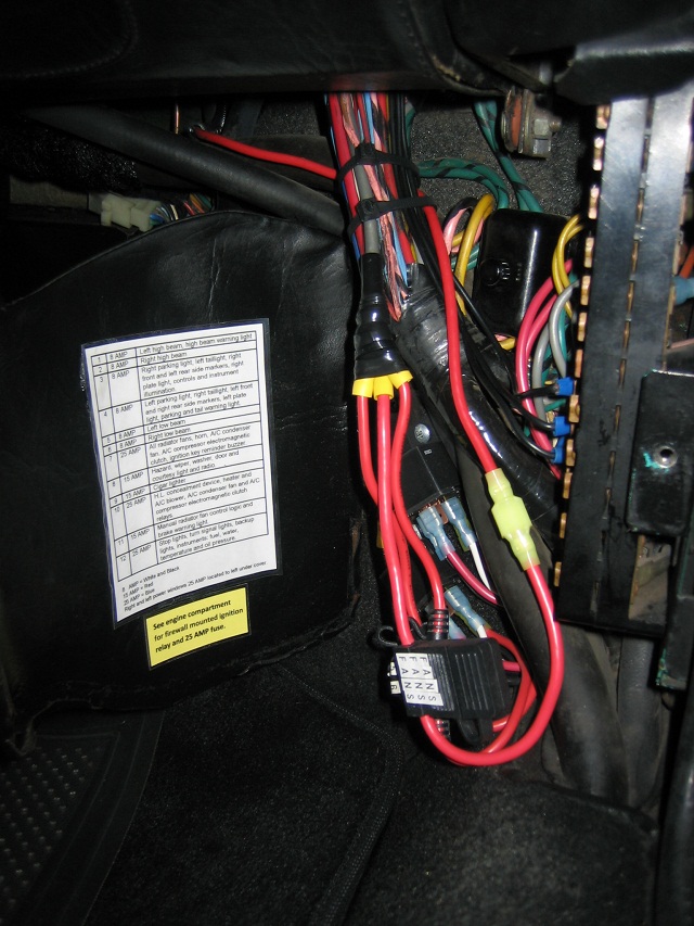
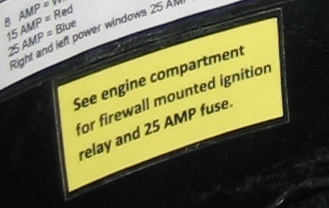
I added a yellow sticker to the fuse panel cover so future owners will know about the relay and location of the inline fuse. I always document changes I make to my Pantera by adding the change information and schematics to 1887s documentation manual and repair log.
November 20, 2011 Follow-up and Conclusion
After running the Pertronix Ignitor III for more than a year I can report that it works very well. Early on in the process the first unit developed an intermittent misfire problem that seemed to be heat related. Pertronix quickly replaced the unit and sent me a note indicating that it had a problem with its power logic.
During the trouble shooting process with Pertronix I added a ground wire from the Ignitor mounting plate to the intake manifold. The Pertronix tech support folks are very helpful. Overall the car starts and runs much better than my original dual point system and I think the process has been very worthwhile. I do carry a spare Ignitor III in the car just incase!