The Pantera Place
"Your de Tomaso
Connection"
The Lower Front Valance Replacement
(Click images to view full size)
Friday, September 24, 1999
Many years ago in the life of my Pantera, someone hit something
with the driver’s side of the lower front valance. As you know the Pantera
has very limited ground clearance so it doesn’t take much to contact the
valance. The bottom part of the valance was crushed along with the lower side
of the front cross member and the front corner of the frame. The cross member
is the square tube across the front of the car with the tabs that support the
bottom of the radiator. About three out of five Panteras I have seen have this
area pretty well smashed. The good news is it is usually painted black so it's
hard to see!
It’s hard to spend a bunch of money to fix a part of the car that is
seldom seen but I decided that I wanted everything right on the car, so I
started collecting the new parts last year. The first part I bought was the
front valance from Pantera Performance for $299. Before this part was
available the complete front part of the car had to be replaced, wow!
Next, I started my hunt for a body shop that I could trust to replace the
parts. Most of the shops that I contacted in Atlanta didn’t have a clue how
to tackle a project like this. To do the work the radiator and cooling fans
need to be removed and I was having some trouble with the idea of a typical
body shop removing the parts and getting the cooling system refilled
correctly. At the minimum, I had to be able to get the car home to complete the system
air-purging, etc. As I talked to the shops it became clear that the more parts
I could provide the better my chances that the work would be successful. Most of the body shops are not setup to make parts other than flat sheets.
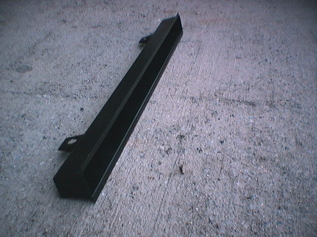
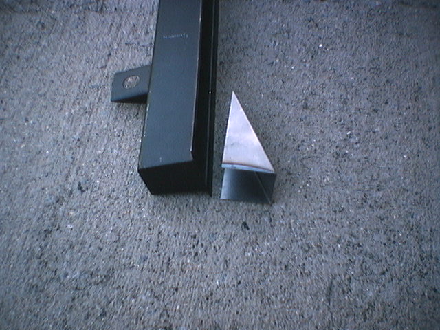
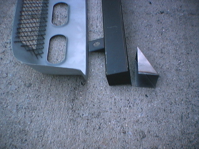
Next, I bought the front cross member and the filler piece that fits behind the
cross member on the driver’s side. The cross member was $175 and the filler
piece was $20.

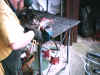
After spending $500 on parts I was able to find an experienced Pantera guy to do the
work. I think I can trust the guy so I delivered the car to him today September 24, 1999, to
start the work. He expects that he will need the car two weeks plus to
complete the work. He also plans to butt joint and hammer weld the valance, so it
could be a winner! The $500 is going to be a small sum compared to the
complete job.
Monday, October 11, 1999
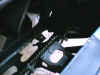
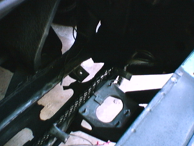
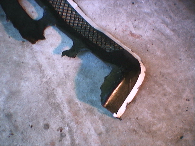
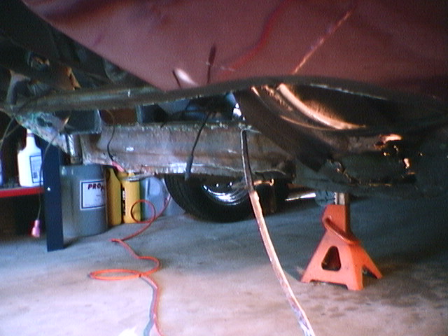
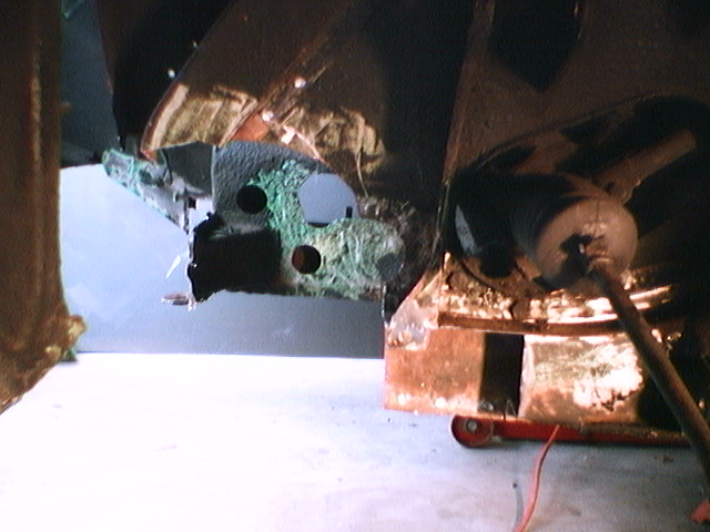
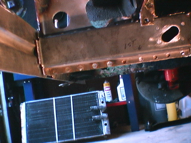
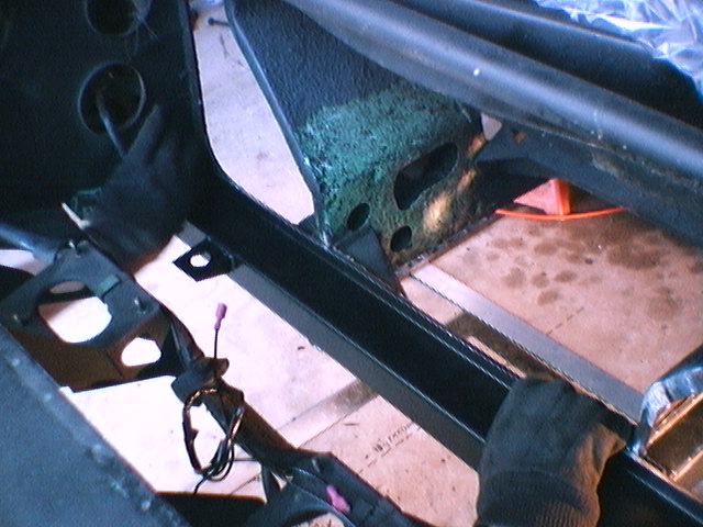
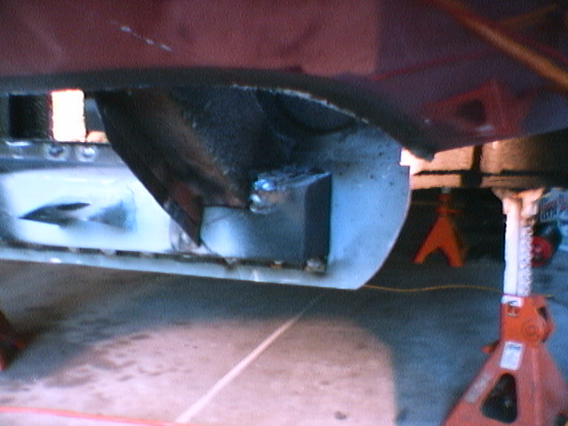
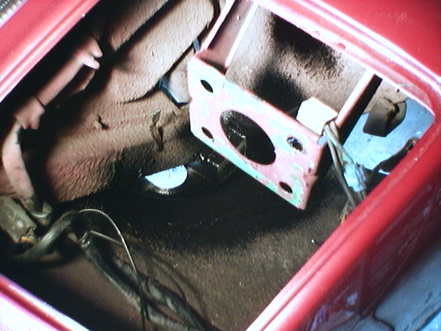
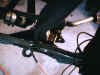
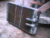
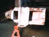
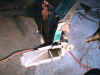
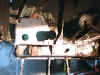
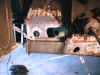
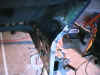
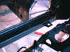
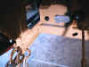
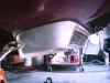
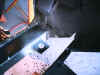
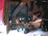
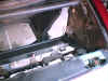
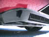
The view of the front valance from the top with the radiator,
front grill work and fans removed. Note the damage to the valance in the
center of the picture. The bottom of the front cross member is also
damaged along with the front corner of the frame rail below the front cross
member. Some of the valance between the vent holes is torn away.
It looks like someone hit something very solid to do this
kind of damage.
Apparently the car has been driving around for decades with
this damage as it looks very old.
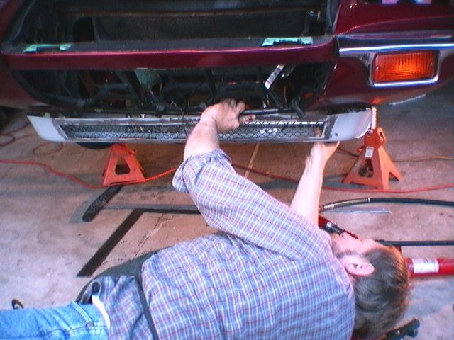
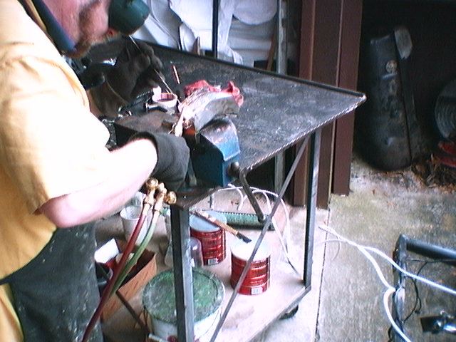
Saturday, October 23, 1999
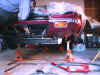
After some delays because of other projects he is now
hard at work on the Pantera. The old valance, front cross member
and driver's side suspension has been removed.
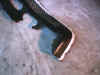
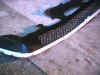
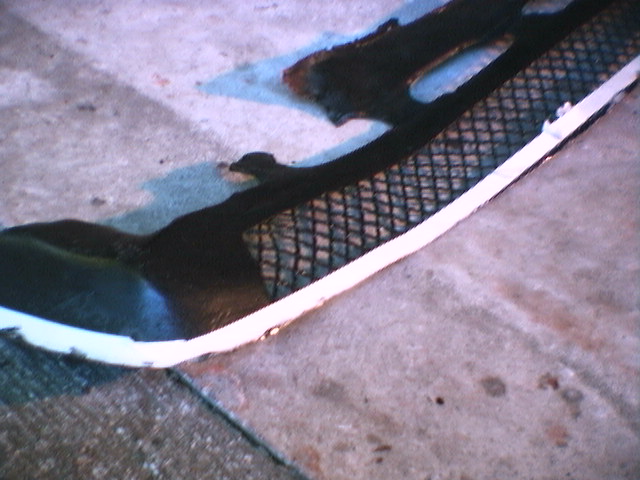
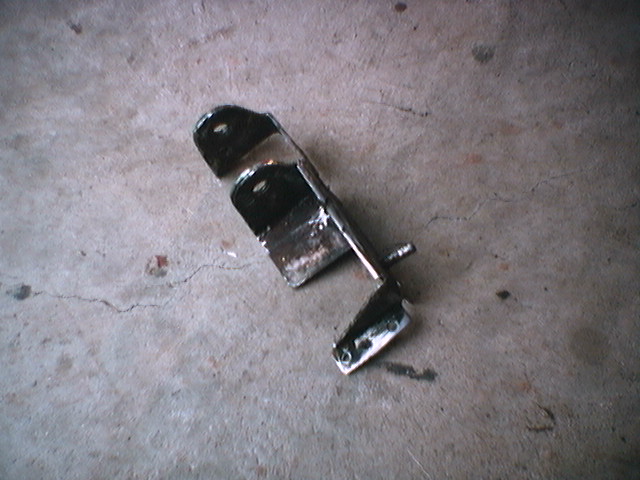
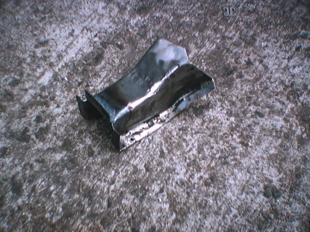
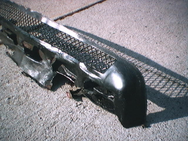
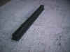
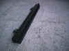
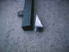
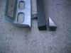
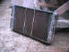
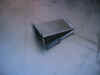
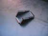
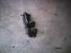
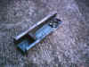
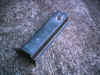
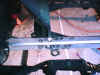
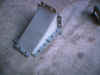
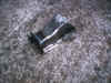
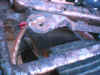
The old damaged front valance and cross member
removed. Note how the lower part of the cross member is smashed.
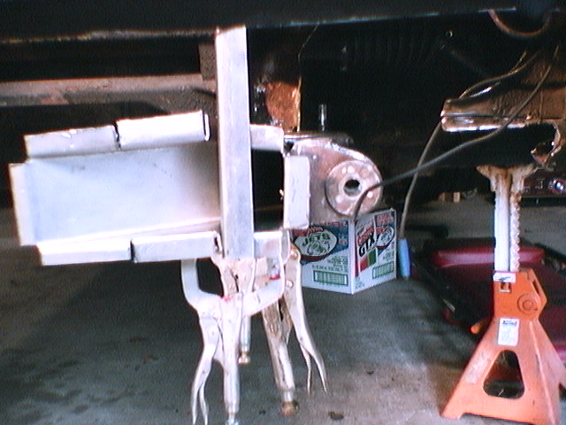
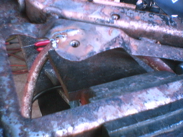
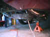
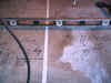
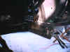
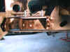
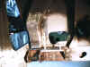
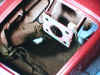
The picture on the right shows the view down from the front of the car.
The front valance and cross member has been removed. The lower front
valance spot weld flange, cross member spot weld flange and the vertical part behind
them was in very tough shape. The water collects in this valance area
and over time takes its toll. After looking at the flange area I'm
not sure how you could just replace the front valance on a typical car.
In my case it was all smashed and needed to be replaced.
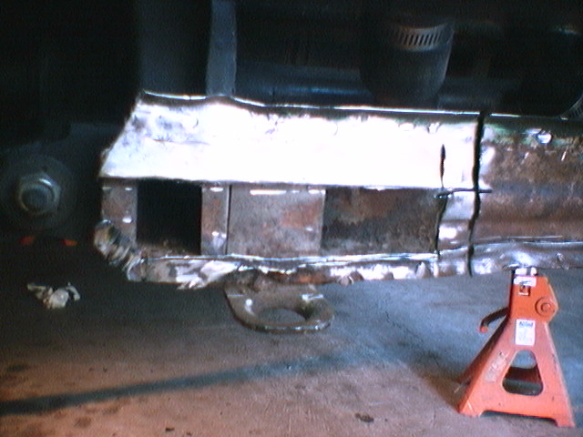
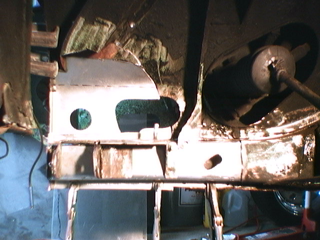
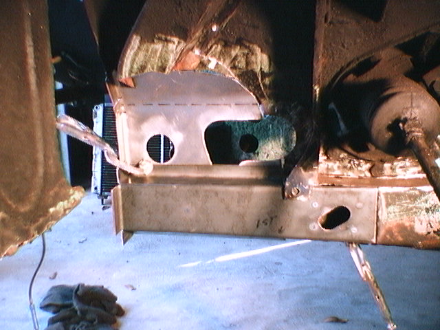
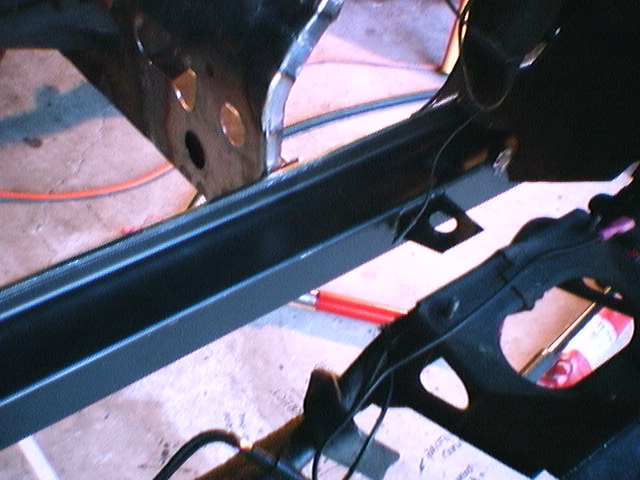
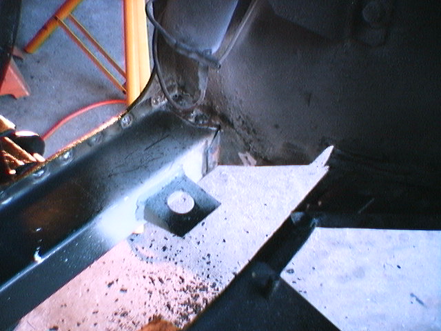
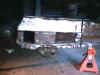
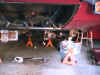
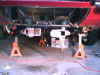
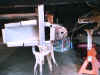
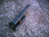
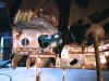
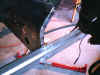
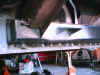
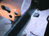
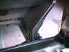
The view from the diver's side across the front of the
car. The front valance and cross member has been removed. The flat
area shown is the sheet metal that is behind the cross member and it will be removed and replaced with
new sheet metal.

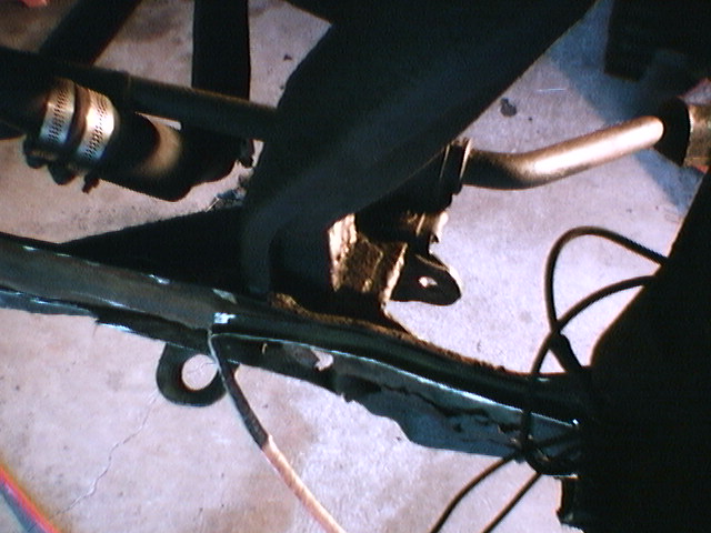
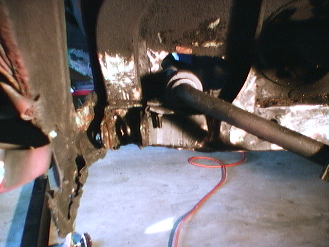
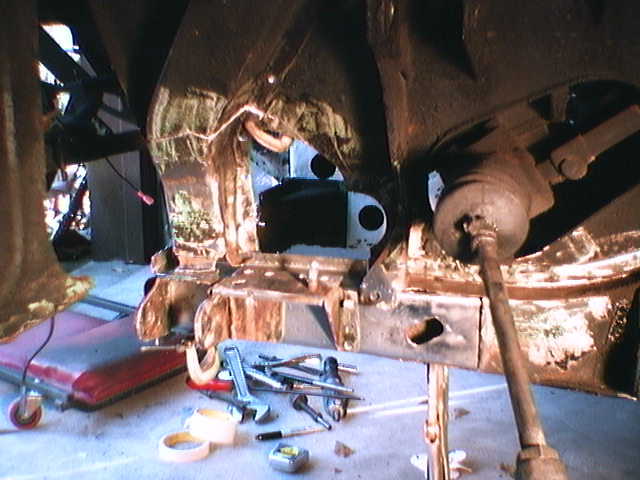
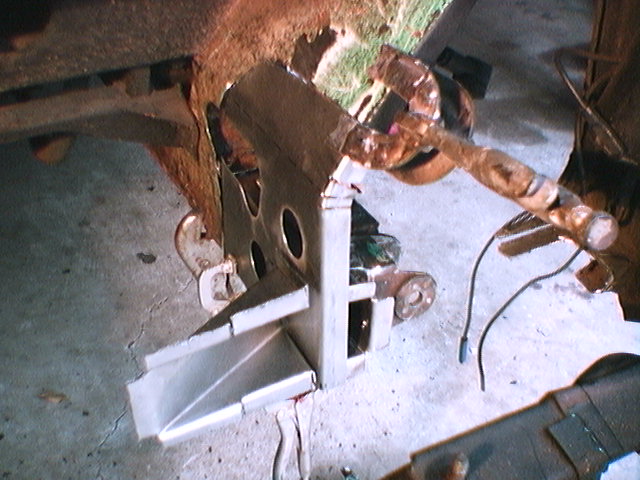
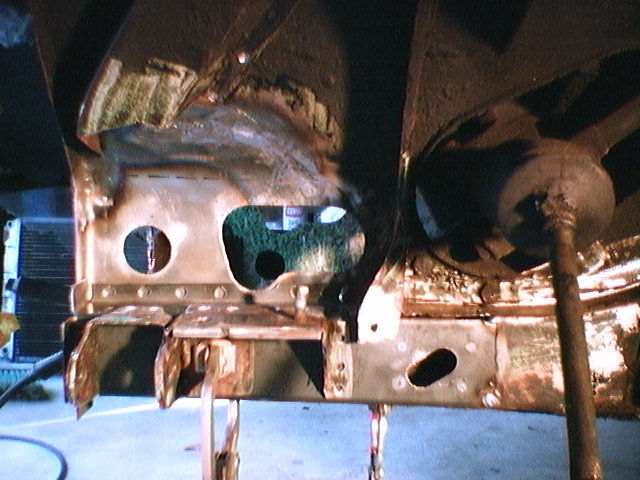
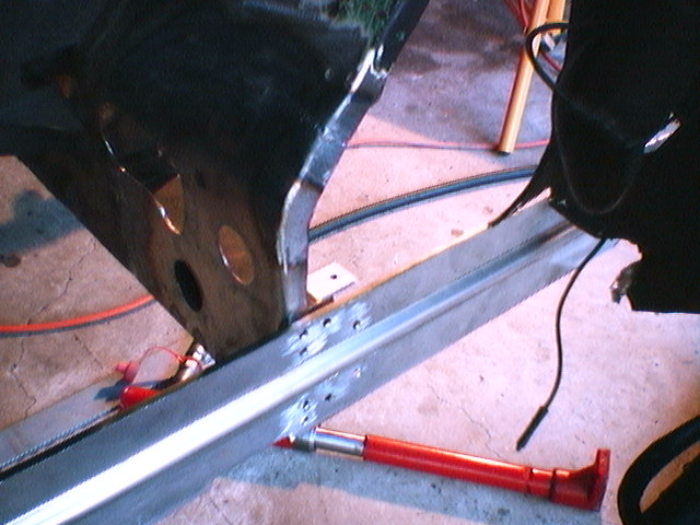
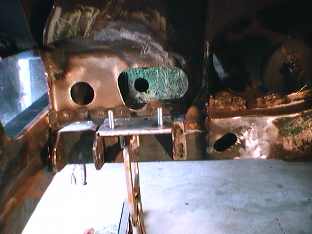
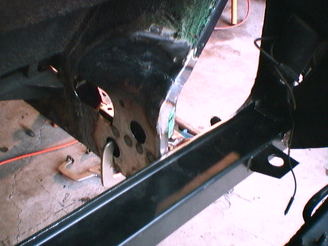
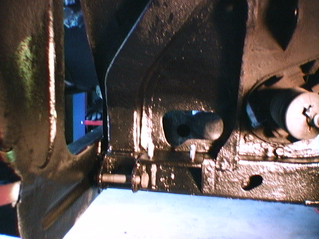
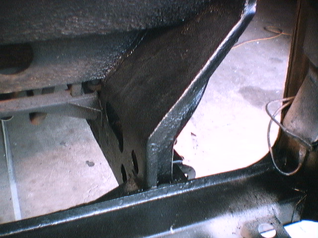
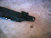
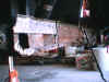
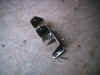
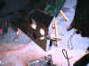
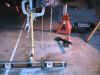
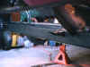
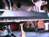
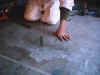
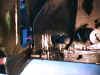
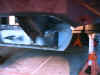
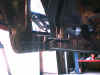
The view of the lower front A arm
mounting. The ragged metal in the lower left corner is the remains of the
back left part of the valance. Note how the front of the frame rail and
the area inside of the A arm mounting is smashed. All of this
frame area must be repaired next. The lower front A arm and sway bar mounting
will be removed. Then the front of the frame rail and sheet metal around
the area will be reworked and repaired. Also the right suspension
will be removed to provide access to the passenger's side of the valance area.
The headlight buckets will be removed for access so that the valance can be
hammer welded back in place.
Although the project has been delayed, it
was smart not to have the typical body shop try this repair!! The
good news is, so far he is right on budget for the project!!!
Wednesday, October 27, 1999
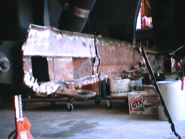
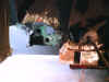
View of the sheet metal that is behind the
cross member being "slowly" cut away to keep from damaging the metal
parts that we are going to keep. The cross member has been removed. Note
that the inside areas of the frame parts have just very, very light surface
rust. This
view is from the front passenger side looking across to the drivers
side. This
sheet metal is also the support part you see behind the left and right end of
the valance. A new sheet metal part will be constructed to replace this
area including the original grooved indentation in the sheet metal that runs across
the part.
After taking a close look at the ball joints
we decided that both lower ball joints had to be replaced. This is an ugly
state of affairs as they are really, really expensive but it needs to be done
right!
We also decided to replace the front brake
pads and will install the new wheel bearings that I bought last
year. He is removing the old A arm bushings to complete the installation
of the new bushings on the driver's side of the car.
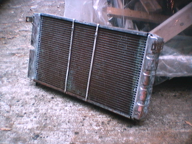
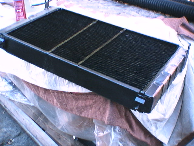
We sent the aftermarket five row dual pass radiator
out to be cleaned and found that the core had some bad tubes. The vendor is
unknown. A new and
improved four row core is on its way to replace the old five row core.
The four row core has wider tubes (front to back) that will improve flow and
cooling. The total thickness of the radiator will be about the same as the
five row core. Many of the old core tubes were clogged with small chunks
of silicone sealer that must be from sealer used to seal gaskets in the
engine. At least two different sealers were present so this must be very
old stuff. This is interesting because I have a receipt from the previous
owner for a radiator clean job dated 1994. When you think about how the
dual pass radiator works you realize that once something gets inside of the
tanks it would be very hard to get it out without disassembling the
tanks. A clean and flush will not clean it out!
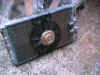
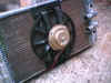
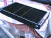
View of the radiator with the new core but unpainted.
He prefers to paint the radiator with high temp epoxy himself rather than the sticky paint
used by the radiator shops. The painting of the radiator is on his
to-do list.
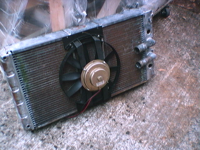
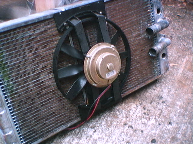
The cooling system uses the two stock pusher fans (I think
they are stock) on the front and one sucker fan on the back of the radiator.
The back fan is mounted to flat sheets of aluminum that are screwed to the upper
and lower radiator frame. The screw holes must be carefully located so
that the screws do not contact the upper and lower cooling tube that is close
to the frame.
The re-core
job was $360 but much less than the two ball joints!
Saturday, October 30, 1999
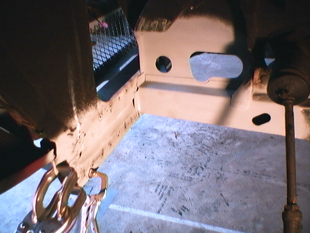
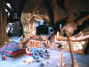
The left picture is the view of the front of
the passenger side frame rail cleaned up and ready for the front to be
assembled. The picture on the right is from the front of the car
showing the exposed and smashed driver's side frame rail. The sway bar
has been removed for access to the right frame area. The next step is
correcting the driver's side frame rail and start assembly. The radiator
will be test fitted in the car before the cross member is welded in place to
check the position of the radiator support tabs. Note all of the work is
being done under the car and will need painting only around the valance
area.
Sunday, November 14, 1999
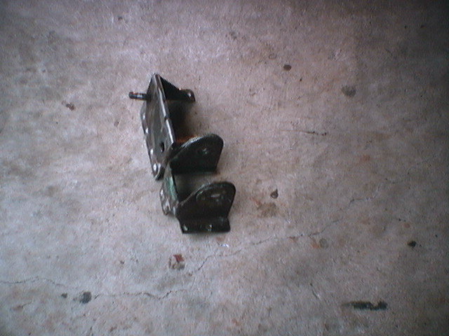
The left front lower A arm/sway bar bracket assembly has been removed and
is ready to be welded back on the new frame rail. The smashed front part of
the frame rail has been cut away along with the flat vertical sheet metal on
the inside of the frame rail that extends upward. The vertical part is the
area that has the hole that the sway bar goes through. The lower part of the vertical frame tube that ties into the top of the front frame rail has been
removed and will be reused. The two metal support parts that were welded
inside of the front frame rail have been removed and will be reused.
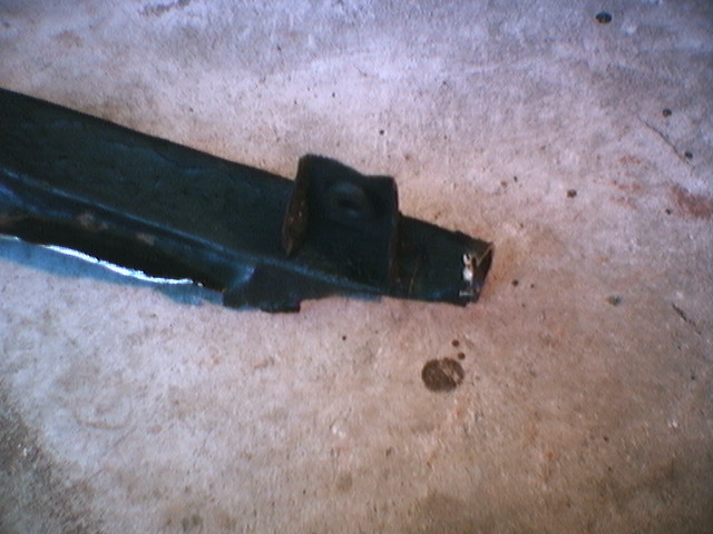
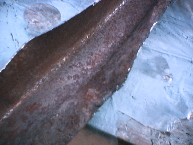
Bellow is the view of the cut away left frame rail in the foreground
and the steering rack boot. The right frame rail is visible in the
background.
New sheet metal is being formed to replace the front of the frame rail, the
vertical piece connected to the frame rail and the metal piece that goes
across the front of the car behind the front cross member. After forming
the new parts they will be wielded in place. Each part must be reassembled in
the correct sequence to provided access for welding. The head light buckets
have been removed to provide access for hammer welding the valance back on.
The horns will also be removed for access.
He used the head light cover to get the paint matched and It looks like
we have a perfect scarlet metallic red paint match although most of the
painting will be done in black. So far twenty shop hours have been expended on
the project with about twenty-four more hours planned to complete the work.
This puts the project within a few hours of the original budget but many more
total weeks of having the car in the shop than originally planned. The good news is that
he is done with the
"taking it apart" phase and is in the assembly mode now!
Wednesday, November 17, 1999, It's Assembly Time!
The view on the left shows the new outside part of the frame rail clamped
in place with the A arm/sway bar bracket camped on for test fitting.
Note that the inside vertical piece is not in place yet. The next two
views show the new corner piece clamped on the frame. He decided
not to use the corner piece that PP made as it did not have the tabs like the
original piece. The new PP cross member will be used as it is an exact
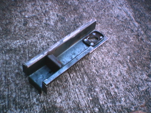
copy. The last two views are the new corner piece he made that is an
exact copy of the original piece including the cut out for the tow eye
piece.


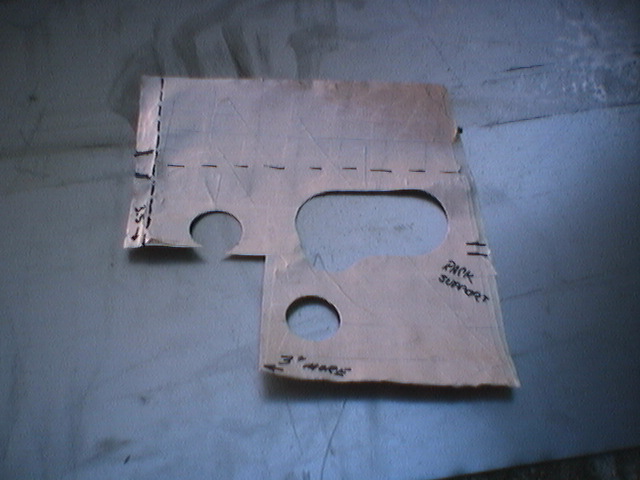
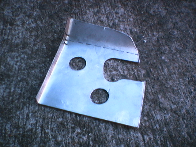
The view on the left is the passenger side template he made that will be
used to cut the piece for the left side of the car. The next view is the
template ready to be used to cut the sheet metal for the left side part.
The lower part of this piece makes the inside of the frame rail. This
piece will be cut so that it fits back in the cutaway part exactly (no overlapping
of parts).
The goal of this project is that when he is done and the under coat is
replaced that all of the repair work will look exactly like the original
factory parts. As I plan to keep this car until I can no longer drive
it's very important that everything is done factory original as who knows what
I might want to do with the car in the future. I might want to go back
to stock wheels and paint and do the show thing! I doubt it but
you never know!
The next steps are, cut out the template piece for the driver side frame,
cut the vertical piece that fits
Saturday, November 20, 1999
View of the driver's inside vertical frame part being test fit.
This is the part that was made from the template of the right side of the
car. The part has some extra metal along the top to be trimmed before it
fits exactly and the oblong hole for the sway bar lines up. The vertical
piece will not be trimmed to fit exactly until the outside frame rail is
tacked in place and aligned. In these views the vertical frame tube that
we are reusing is not in place. This part will cover the round hole
right above the A arm mount.
View of the A arm and sway bar mount that will be reused
He is constructing the front flat sheet that fits behind the valance
and was making the bead or grooved indent that runs horizontally across the
part when I was at the shop. The welding should start on Monday.
The next steps will be to weld in the two small brace parts that fit
inside the frame rail and then tack the outside rail in place.
Then align the rail and tack the inside vertical rail part. The parts
must be assembled in
sequence to give access for
welding.
Thursday, November 25, 1999
His work progress has been delayed because the front flat sheet with the bead has
been very difficult to make. He had to make some jigs to make the bead
roll but has the part almost done. It has taken three parts to get it
right! He has an interesting approach to this issue. He only
charges for the time it takes to make the last completed usable part.
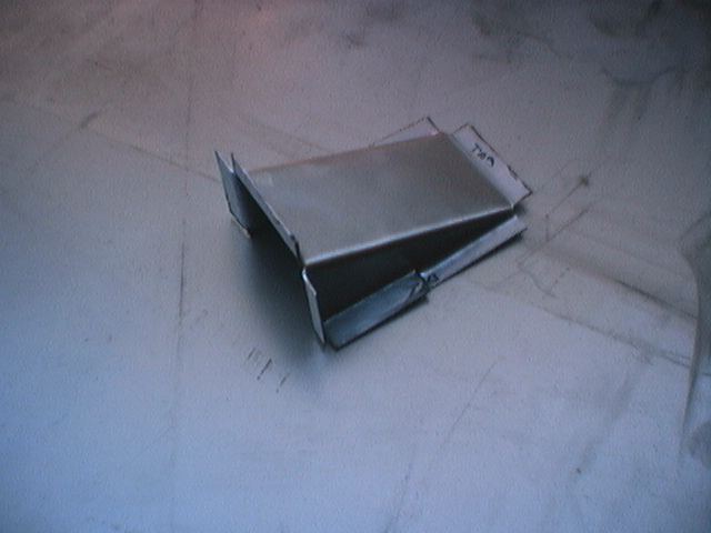
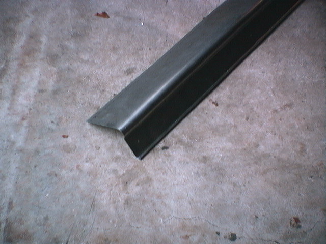
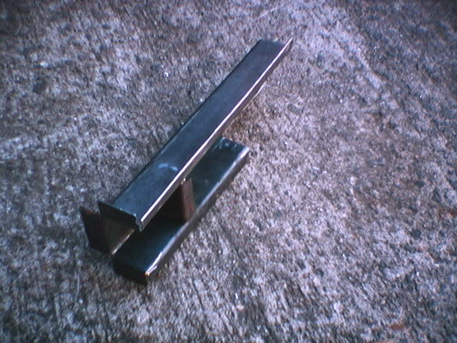
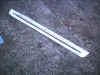
View of the front flat sheet. The top edge is to the right side of
the image. The bead has been rolled in the part but one more bend
will be required on the left side of the bead to make the part flat and
maintain the bead roll. After the part is flat, the bead will be
removed on the outside ends to match the original part. It would have
been easy to use a bead roller to make this part but the bead is much larger
than a regular bead roller can make. The top part has a bend that
matches the original part. One might think about giving up on the bead because it is so difficult
to make but it will look right and is needed because the ends of the A arm
bolts enter the open space provided by the
bead.
This part extends across the front of the car
behind the front cross member. It is welded to the front frame rails,
the corner pieces, the vertical flat sheet that support the bottom of the fenders,
and is the lower back part and sides where the front valance is
attached.
Thursday, December 2, 1999, It's Welding Time!
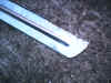
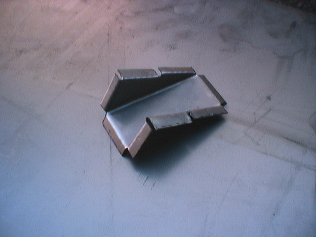
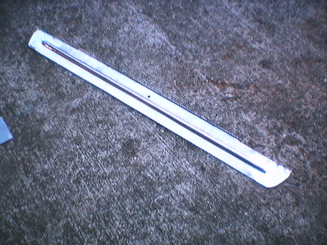
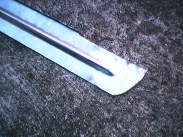
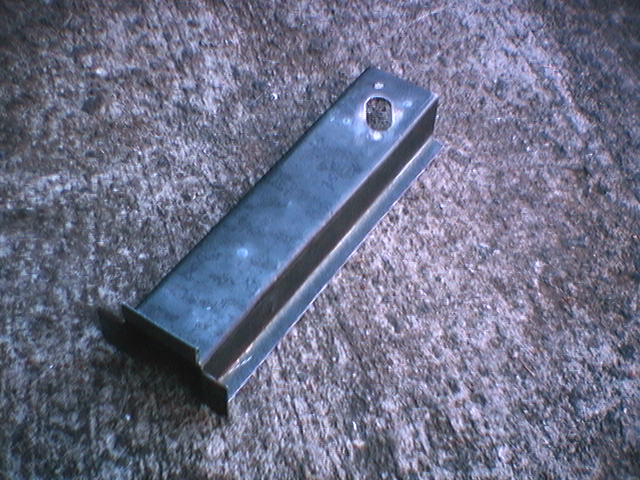
The front flat sheet is complete with the bead and looks great.
Note how the bead stops at the outside ends. Tricky stuff for sure!
The inside support parts are welded inside the frame rail. Note how
he is duplicating the look of the original spot welds. This is the
second frame rail as the first attempt did not fit correctly. This is
another tricky part as it has a very slight taper! The first part had
too much taper.

View of the inside frame part and the frame parts being test positioned to
start the welding process.
We decided to add three water drain holes along the bottom side of the
front cross member and the lower part of the front valance. It is
amazing what a great water trap this area is! Once water splashes inside
the valance grill or gets inside the front cross member there is no way for
the water to drain out. For some reason my car did not have much rust
along the lower part of the valance or the cross member. It was mostly just
smashed with rust along the spot weld flange at the bottom! The inside of the areas will be primered before they are welded
closed.
It has been a lot of work but the end is in sight! He is
starting to mumble in a foreign language that sounds Italian to me! Something
about "Ghia" or "de To - - -" something!
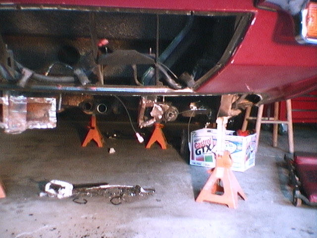
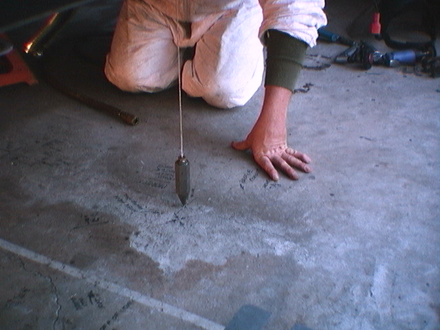
Saturday, December 4, 1999
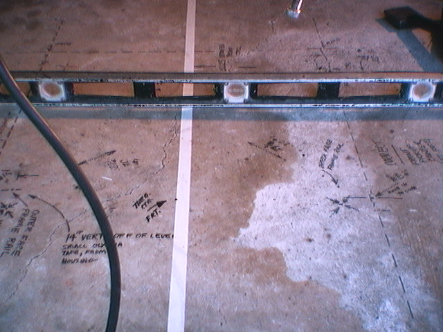
The back of the car was leveled
on jack stands using the lower A arm mounts as reference points. Then the centerline of the car
was projected on the floor below the
car. The front of the car was checked for level using the front A arm mounts
and factory data points as reference points. The
back of the front A arm mounts were used as the left front mount was removed. The right lower front A
arm was removed and the center of the A arm
mounts projected down to the floor using a plumb bob. Note the center line on the floor
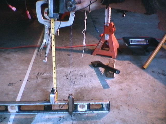
and lines and data points in the above images. In the image above on the
right, a plumb bob is used to check the position of the left front A arm mount.
The level is used as a level base point across the floor to check the height and
position of the new left frame rail. When he is done I may have
the squarest and most carefully aligned Pantera around!
View of the outside and inside frame rail parts in place. The A arm
mount is clamped in place to test fit the placement. The inside vertical
frame has been hammer welded in place and the outside frame rail is tack
welded in
the back and spot welded along the lower flange. Note the way the the
new parts interlock with the existing structure but none of the metal
overlaps. Butt joints are used throughout to connect the new parts
except for the factory overlapping flanges, etc. The hammer welding process
creates a very strong weld but has a smooth seam. With very, very light grinding
or in some cases just sanding the welded seam is completely invisible. Hammer
welding is a welding process (fine art) where the weld is hammered with body
tools while the weld is red hot creating a smooth finished seam.
Note the small holes drilled along the top flange of the outside frame
rail. The part will be clamped and then welded in each one of the
holes. This duplicates the factory spot weld look but is much stronger
than the original spot weld.
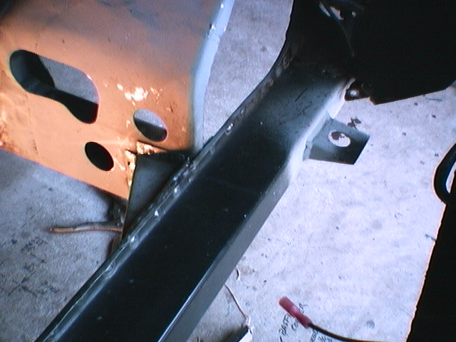
Saturday, December 11, 1999

View of the lower edge of the frame rail with simulated
spot welds. A small hole is drilled on the flange and then MIG welded through
the hole to the inside flange material and filled to the outside flange.
Some of the welds are complete along the front part. It looks great,
just like the original spot weld.

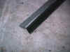
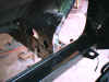
View of the vertical part that fits behind the cross member and
connects to the lower part of the fenders. Note how the folded
over top edge mates with the folded part on the back side of the fender.
The front A arm mount
will be welded in place after the vertical part is fully welded in
place. In the image on the far right you can see the alignment of the
vertical piece with the lower edge of the fender. He found that the
lower part of the fender had been pulled back some by the blow to the valance
and cross member. A port-a-power was used to move the lower part
of the fender forward to the correct alignment. He was able to
move the fender forward without damaging any of the paint elsewhere on the
fender.

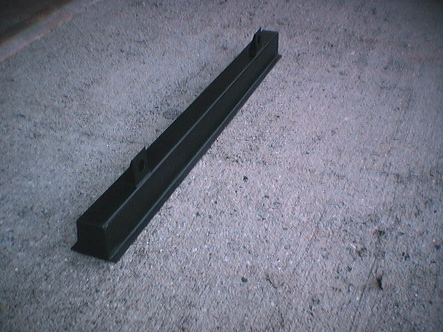
View of the front cross member being test fit before the
remaining welds are completed on the vertical part behind the cross
member.

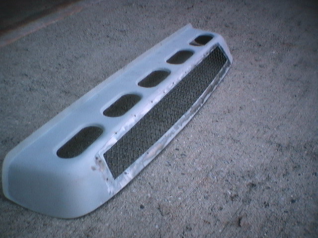
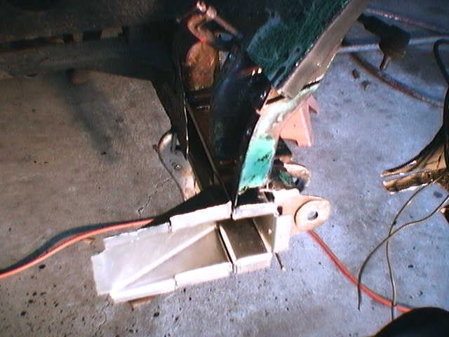
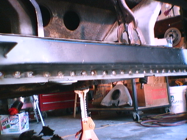
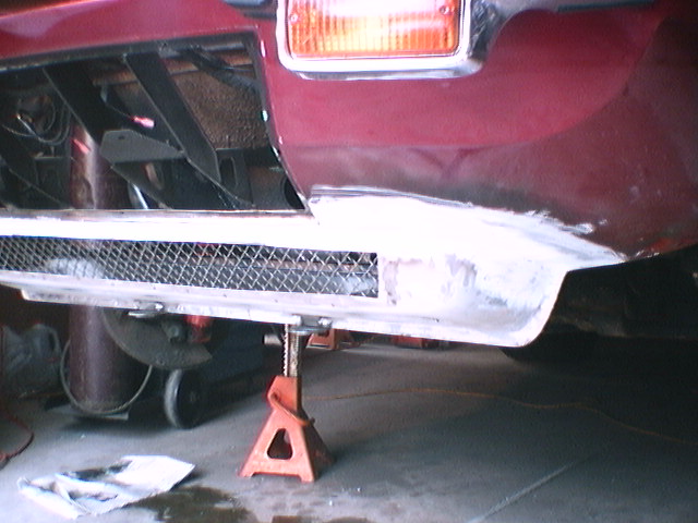
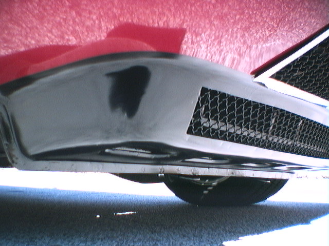
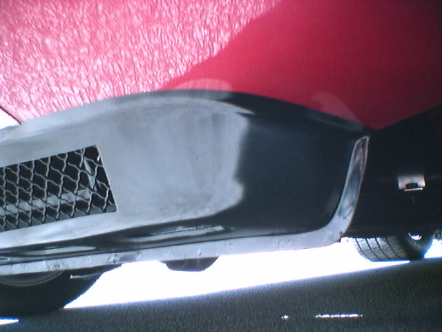
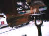
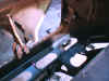
View of his test fitting the lower front valance.
After all, the front valance is what this project is all
about! Check out the original green paint around the hood hinge
mounts. It's great to see the parts being assembled after all these
weeks! We keep thinking that it will just be another week but then
he gets pulled off my project on others so progress is slow. Although
the progress has
been slow but as you can see his work is very outstanding! This is
the kind of project where careful planning is important. It is an
amazing amount of work to fix something that no one will ever see!!! Although,
since I started this project the front valance is the first thing that I look
at on Panteras!! Most of them are not looking very good!
Tuesday, December 14, 1999

The view on the left and middle shows the completed welds
on the frame rail and the front vertical piece. The front vertical piece
is welded to the vertical part of the inner fender support. The A arm
mount will be checked for position and will be welded in place after the front
cross member is complete. After the A arm mount is completed, the vertical
frame tube will be welded in that connects from the top of the A arm as seen
in the image on the left. The image on the right shows the front
cross member being test fit. It looks like the radiator mounts on the
cross member need to be lowered 1/2" for the radiator to fit correctly.
The remaining things to do are; weld in cross member, weld
A arm mount, weld in vertical tube frame, weld in frame corner part and the
driver side tow eye, prime exposed areas and paint flat black, weld valance in
place, prime and sand valance, paint red color around valance, paint
valance flat black, undercoat frame areas, assemble the right and left suspension,
install sway bar, paint the radiator, install the radiator and fans,
fill system with coolant and bleed air out of system. Then fire it
up and drive it home!
Friday, December 24, 1999
On the left, the view of the new frame rail with the valance being test
fit. View on the right is the right side of the car. Weld through primer is used on the inside and outside of the parts
before welding. From what I can see the inside of the original parts
that we removed were not treated with anything.

View of the inside of the old cross member. Some of the inside areas of the front cross member had spots
with NO surface rust.
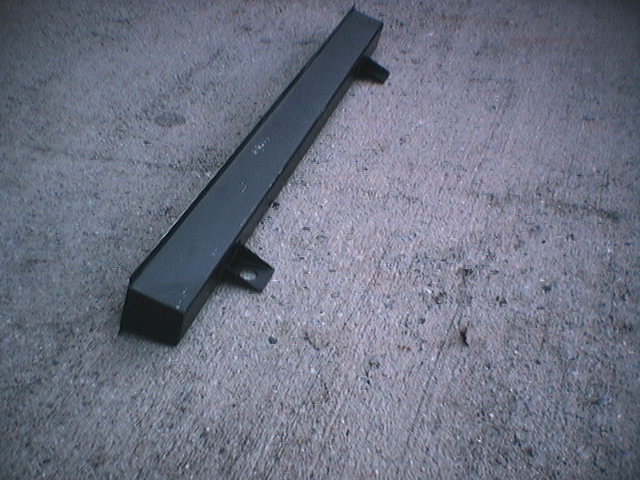
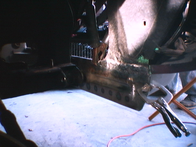
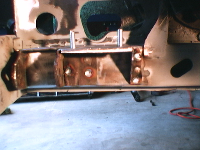
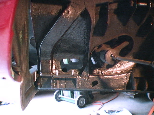
View of the front cross member spot welded in place. He had to
lower the radiator mounting brackets about 1/4" to make the radiator
fit correctly. The welds on the end bracket are not completed yet.


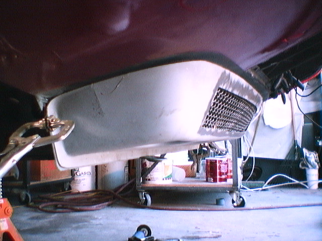
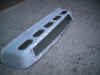
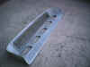
View of the front valance ready to be welded in
place. Note how the lower part of the valance fits tight up to the lower
side of the front cross member. A great place to trap water! After the
valance welding is complete the lower spot weld flange and the vertical piece
behind it will be trimmed smooth along the lower edge.

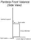
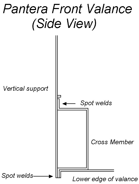
On the left is a detailed drawing showing all frame and support
parts, how they fit together and a description of what was done with each
part. On the right is a side view of the cross member and
valance showing how parts fit and spot weld points.
Thursday, December 30, 1999
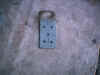
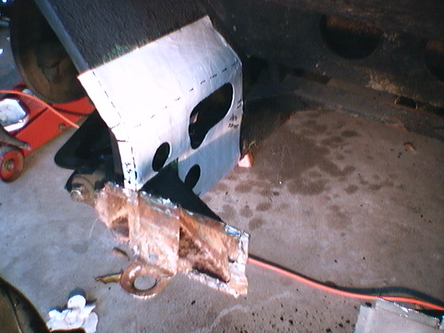
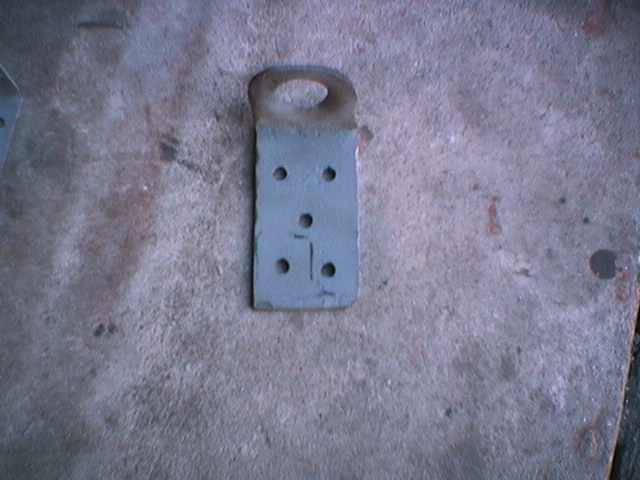
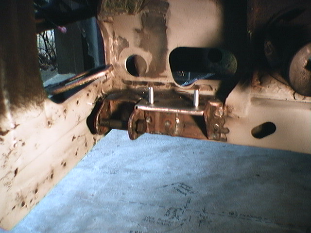
View of the driver's side tow
eye and corner fill piece drilled for the spot welds and ready to be welded to
the front end of the car. The tow eye will be spot welded to the
back side of the new lower vertical support. The parts manual shows
the tow eye on the front of the support but on my car it was on the back
side. I think the parts manual must be wrong! The corner fill piece has
a stepped area so that it can cover the vertical part of the tow eye and be
spot welded to the back side of the vertical support and the inside frame
rail.
All sides of the parts are coated
with weld through primer before assembly to prevent rust problems. Too
bad de Tomaso didn't have weld through primer to use on the cars in
1971! Weld through primer is a special self etching primer that apparently
does not interfere with the welding process. The primer stays on the parts during
welding including the inside of the flange seams.
There are a lot of open areas
of the Pantera bodywork and suspension mounting areas to collect and trap
water that do not have a path for the water to drain away. See the round
holes in the views below. It is
somewhat amazing that these areas are not completely rusted through on most
Panteras. Some people drill drain holes in the water trap areas or drill
the areas and spray rust proofing paint inside the parts with special spray nozzles.
My solution is to not get the car wet.
Friday December 31, 1999

View of the driver's side tow eye and corner fill piece
welded in place. We started having problems welding with the weld
through primer. The primer must be used with a light coat or it gases
off bad stuff when welding. We decided not to use it under the A arm
mount flanges.
On the left is a view of him checking the position of the
A arm mount before welding. The plumb string is through the front A arm
mount ear hole. He is checking the position with the alignment marks
that were projected on the floor. Before starting the final check
of the A arm position, he rechecked to make sure the car had not moved on
the jack stands and
was aligned with the floor references. The A arm is checked for
right/left, up/down and front/back position. He left the A arm mount installation
as one of the last major welding tasks in case any of the other welding moved
the frame rail position. All of this stuff must be dead on alignment.
On the right is a view of the A arm mount with some of the
spot welding done.
The spot welds look really good!! It only takes the MIG welder a few
seconds to make the spot weld. We were able to reuse the A arm
mount because he very carefully cut the old frame rail parts away from the
mount. He sacrificed the old crumpled frame rail parts to save the
complex mount assembly. New sway bar studs were welded in the mount.
Saturday, January 1, 2000
Well, I guess this is now the millennium Project!!!

View of the A arm mount completely installed
and aligned perfectly. He had some problems getting the mount aligned
correctly, slowing progress on the project. Getting the A arm
mount located correctly was absolutely one of the most critical parts of this
project
On the left, He is gas welding some new tabs on the
vertical frame tube that fits on top of the A arm mount. Center,
is the view of the completed frame. On the right, is the view of the
frame being test fit. The flanges on the part must be drilled for
the spot welds, then clamped in place and welded. The top seam will be
gas welded.
Wednesday, January 5, 2000
Before
After
Before and after view of the completed A arm and vertical
frame installation. This area was primered and then covered with paintable
undercoat. To make the new undercoat blend into the old undercoat smoothly
he feathered the edges of the old undercoat. When the undercoat is
fully dried it will have a dull finish. With the undercoat completed,
the frame area looks just as it did in 1971.
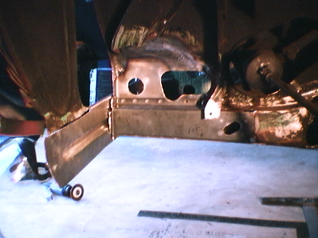
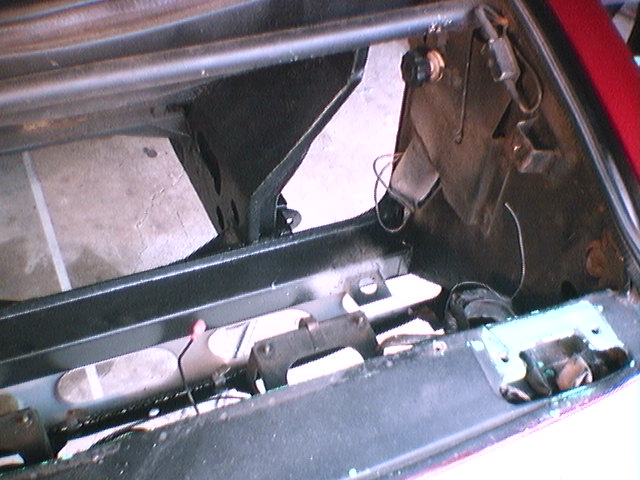
View of the front valance area ready for the
valance to be spot welded
in place. Before the valance could be installed more welds had to be completed
and a small tab repaired where the inter-fender support pieces attach to the front cross
member. This area will painted with primer and some of the upper
areas undercoated before the valance is welded in place.
View of the upper side of the A arm sway bar
mount. On the older cars a crack will form beside the sway bar mount bolt
hole. He is welding the crack and will weld in support tabs on
the lower side of both lower A arms. Sway bar mount support tabs were used on the later
cars that wrap around the threaded area and were welded at an angle to the
edge of the A arm. He made a template of the support tab from a 1974
car. The A arm has been cleaned with oven cleaner and will be
sanded and painted flat black.
The outside of the radiator was given a
final cleaning and painted with gloss black high-temp epoxy paint.
Saturday, January 8, 2000, The valance is
on!
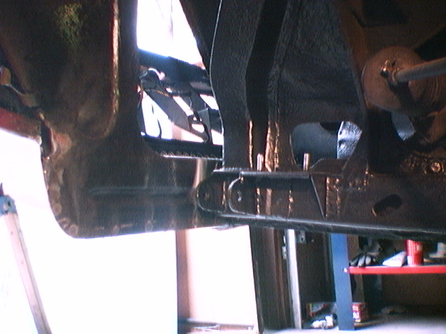
On the left is the view of the inside frame
complete with undercoat and on the right is the view of the frame and the back
of the valance. The undercoat looks really great!!! Other than the
new undercoat there is no trace that he did all of this work!! It all
looks factory original!
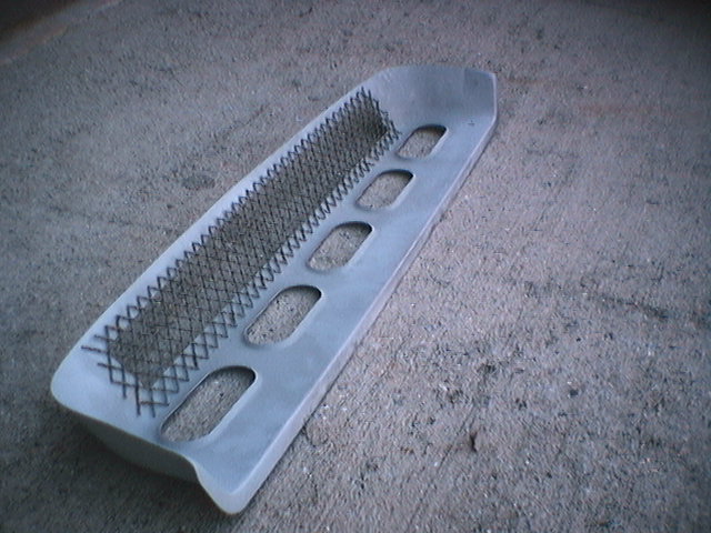
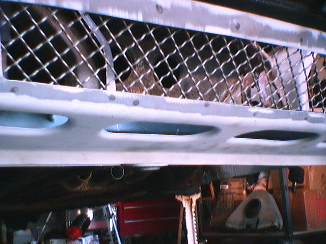
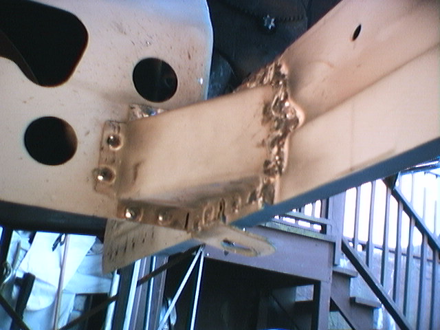
Views of the valance from the back and inside areas.
It is hard to see, but in the center picture it shows that the inside welded
valance seam is not visible and is smooth. He had to gas weld the top
valance seam as the MIG welder on the lowest setting would cut through the new
valance part. The top edge of the new valance had to be cut, fit and
worked so it matched the fender joint exactly. The lower valance flange
was clamped and spot welded. The top of the valance was butt joint fitted
to the fender piece and hammer welded to form a smooth seam. This
was done by tack welding along the seam and then going back and filling in
with weld and hammering.

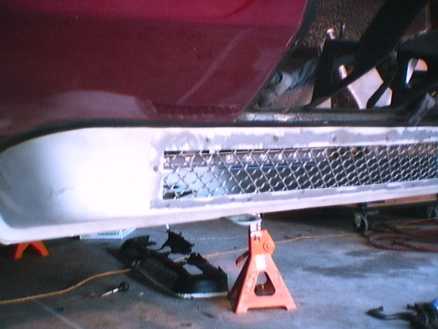
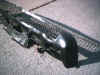
View of the completed valance
installation. A small amount of filler has been applied to the upper valance
seam and will be mostly sanded away to form the final seam radius.
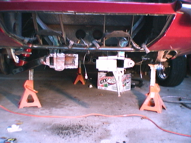
The back wheels are on and the back of the
car is off the jack stands. Next, he is doing some primer work and the
color painting. As the paint is drying he will re-install the front suspension.
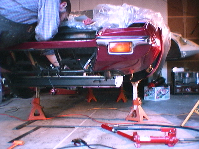
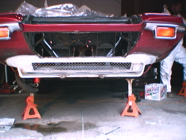
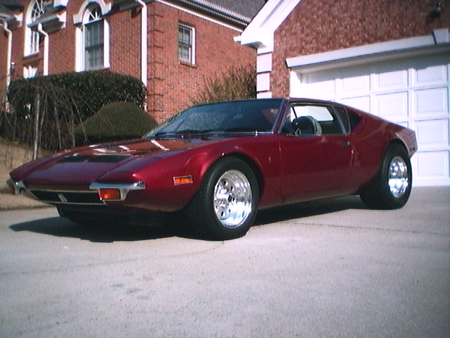
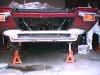
Friday, January 14, 2000, It's done and
the car is home!
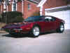
It's done and
the car is home!

Before and after
After more than three months the beast is
home. As you can see his work looks really, really good!!!
It was so fine to get back in the Pantera after all these months and drive it
home........ it was almost like the first time!!! Man that camed-up 351
sounds fantastic!!
Project Summary
The original project plan had 42.4 hours plus
$260 for paint and supplies. We easily used the 42.4 hours plus 33 hours or more
to complete the project. Most of the
extra time was used to remove and reconstruct the frame rail and the A arm
mount. The original plan was to just repair the smashed frame rail parts but
that was not possible.
Other unplanned hours were used to manufacture
a new corner frame fill piece, install new A arm bushings and grease fittings in
the left A arms (I had already done the right side), add the sway bar mount
braces, install new ball joints, brake pads and repack the wheel bearings (we didn't
use the new ones as the originals were like new).
Overall the project turned out well and his work looks fantastic. After this experience and seeing up-close how
the front of the Pantera is constructed I expect that on most cars the idea of
just replacing the valance piece alone is probably not realistic. In most
cases the water that collects in the valance area will have taken its toll on
the vertical support behind the valance and the bottom of the cross
member. You really can't determine the condition of the lower part of the
cross member until the valance has been cut away. In my case it was
smashed so it was an easy decision to replace all of the parts.
In summary, it was the single most expensive thing
that I've done to the car so far but on the other hand most Panteras need a new
valance. My Pantera is now the exception to that rule!!
November 28, 2000
After the valance work I completely rebuilt the back suspension and then
had a wheel alignment done. All of
the alignment worked perfectly and I was very pleased to find that the left
front of the car aligned correctly after all of the work that he had done to
the left frame rail and cross member.
Thanks to the craftsmanship the
front to back position of the left front wheel was within .030 inches of the
right front wheel and the caster was within .4 degrees . The lateral
alignment position of the back wheels to the front wheels was within .020
inches.